
Why Pneumatic Manifolds Cause Uneven Actuation—and How to Correct Pressure Drop
Uneven cylinder movement is often blamed on a weak compressor or a faulty actuator, yet the underlying restriction may sit inside the pneumatic manifold. A machine can show normal regulated pressure while idle and still lose enough pressure during a fast stroke to delay one cylinder, weaken a clamp, or cause two nominally identical actuators to reach their end positions at different times. The reason is simple: static pressure at the inlet does not prove that sufficient air flow reaches every working port when demand rises.
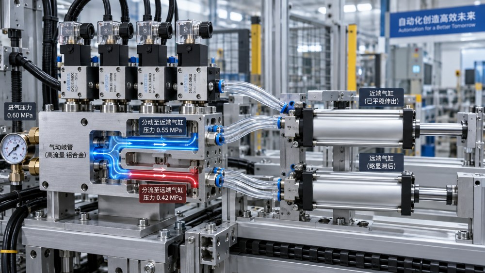
A manifold distributes compressed air through internal galleries, valve interfaces, ports, fittings, and outlet connections. Each passage imposes resistance. When several valves shift together, the available flow must pass through shared upstream geometry before it divides into branch circuits. If that geometry is undersized, contaminated, poorly sealed, or configured around unequal loads, pressure at the cylinder ports can diverge sharply during motion even though the supply gauge appears stable.
Read the Symptom as a Flow Problem First
Pressure drop becomes important when air is moving. During a cylinder extension, compressed air must fill the increasing volume on one side of the piston while exhaust air leaves the other side. A restrictive manifold path slows filling, so pressure builds gradually instead of promptly. The cylinder may hesitate at breakaway, travel slowly through part of the stroke, or lose force as external resistance increases.
Compare the pattern before changing hardware. A cylinder that is slow in both directions points toward an undersized feed, restricted valve, blocked silencer, long tubing run, or general supply limitation. A cylinder that extends normally but retracts late often has a problem on the opposite valve work port, the exhaust route, or a flow-control setting. If two cylinders become uneven only when they operate together, shared manifold capacity and simultaneous peak demand deserve more attention than either cylinder alone.
Clamping systems create a particularly misleading symptom. The gauge upstream of the manifold may show the expected regulated value, while pressure at the cap end of a cylinder falls during clamp closure. The clamp can touch the workpiece but fail to develop repeatable holding force. Raising the regulator setting may conceal the restriction temporarily, but it also changes impact energy, seal loading, and the behavior of circuits that were already correctly supplied. The useful measurement point is as close as practical to the valve outlet or cylinder inlet, observed while the demanding motion occurs.
Where the Loss Accumulates
Manifold pressure drop rarely comes from one dramatic blockage. It is frequently the combined effect of several modest restrictions. A small inlet thread, a reduced-bore quick fitting, a narrow manifold gallery, and long small-diameter tubes can together limit a circuit that looked adequate when each component was considered separately. The smallest effective cross-section often governs the usable flow path.
Port labels alone are not enough for selection. A manifold may have an inlet connection large enough for the main line while its internal gallery or valve mounting interface is intended for lower flow. Likewise, a valve's nominal port size does not describe every internal turn, spool passage, gasket opening, or interface cavity. Flow capacity information from the valve and manifold should be treated as a matched system, especially where multiple cylinders are expected to move at once.
Internal geometry also matters. A long manifold with a single end feed creates a pressure gradient along its length whenever several stations consume air. The valves nearest the inlet receive air before the furthest stations. The difference becomes most visible during rapid cycling, high-volume cylinder strokes, or concurrent actuation. A center-fed or dual-fed arrangement can shorten the shared flow path, but it only improves balance when the supply branches feeding those points are themselves adequately sized and regulated consistently.
Restrictions that are easy to overlook
- A blanking plate, gasket, or valve interface seal installed in the wrong orientation can partly cover a gallery opening. The circuit may still function at low speed, which makes the defect appear intermittent.
- Thread sealant applied too far into a port can extrude into the passage. Loose tape fragments may travel downstream and lodge at a valve pilot or a flow-control needle.
- Push-in fittings with an unexpectedly small bore are common bottlenecks. Their outside tube size can look appropriate while the internal opening is materially smaller than the tube bore.
- Exhaust silencers gradually load with oil residue, dust, or fine debris. Restricted exhaust raises back pressure on the rod side or cap side, reducing the pressure difference that actually moves the piston.
- A manifold repair that mixes valve generations or mounting patterns can leave a mismatch at the sealing face. Similar external dimensions do not guarantee the same port map or gasket window.
Pressure Is Not the Same as Available Force
Cylinder force comes from pressure difference across the piston, not simply from supply pressure. On extension, cap-end pressure must overcome load, friction, breakaway force, and any pressure remaining on the rod side. On retraction, the smaller annular piston area changes the force relationship. A circuit can therefore appear balanced in an unloaded test and become uneven after tooling, guides, seals, or process resistance are introduced.
Side loading makes this distinction more important. A cylinder with a misaligned clevis, worn guide, bent rod, or binding slide demands more breakaway force than its paired cylinder. The manifold may then appear responsible because the higher-demand branch shows a larger transient pressure loss. That loss is real, but increasing gallery size alone will not correct the mechanical source of demand. Isolate the actuator by disconnecting the load where safe and permitted, then compare its travel behavior with the loaded condition.
Temperature and lubrication can shift the diagnosis as well. Seal friction often rises after a cold start, while heavy lubricant carryover can alter valve response and attract contamination. A fault that occurs only during the first cycles may reflect mechanical resistance or sticky valve internals rather than a continuously undersized manifold. Conversely, a restriction caused by accumulated debris often worsens over time and may affect one work port more than the other.
Measure the Drop During the Event
A meaningful test captures pressure under dynamic demand. Record or observe supply pressure upstream of the manifold, pressure at the manifold inlet, and pressure near the affected valve outlet or cylinder connection. Repeat the same motion under normal load, then compare it with a single-cylinder test. The location where the pressure reduction first becomes significant narrows the search.
If supply pressure remains stable but manifold-inlet pressure falls, inspect the feeder line, isolation valve, filter-regulator assembly, couplings, and inlet fitting. If the manifold inlet remains stable while a downstream work port drops, concentrate on valve capacity, valve condition, gasket alignment, work-port fittings, tubing, flow controls, and cylinder demand. A pressure reduction that appears mainly at exhaust should not be treated as an inlet deficiency.
Response timing adds useful evidence. A valve command that is delayed before air begins to enter the cylinder suggests an electrical, pilot-air, spool, or control issue. Air entering promptly but the cylinder accelerating slowly points more strongly to flow capacity, exhaust back pressure, or high mechanical resistance. These faults can coexist, so replacing a solenoid because a cylinder is late can produce a short-lived improvement without removing the restriction.
Correct the Restriction Without Creating a New Imbalance
Start with the condition that can be verified. Clean or replace contaminated filter elements, drain accumulated water, inspect silencers, and remove damaged fittings or crushed tubing. Replace fittings by confirming their actual flow bore, thread type, and tube compatibility rather than matching outside appearance. Tube runs should be as short and direct as the installation permits, with bend radius maintained so the bore is not pinched.
When manifold capacity is insufficient, select a layout based on the combined demand of the circuits expected to move together, rather than on the requirement of one cylinder. Consider cylinder bore, stroke, cycle time, number of simultaneous strokes, expected load, and the need to refill the actuator volume before the required motion completes. A manifold intended for small pilot valves may be unsuitable for a bank of larger directional valves even if the thread connections can be adapted.
Feeding the manifold at more than one location can improve distribution on long valve banks. It should be planned as a balanced supply arrangement, not added casually with unequal restrictions or separate regulators set to different pressures. Where a circuit needs deliberately different pressure, use a properly located pressure-regulating element and recognize that it changes the force available to that actuator. Do not use a partially closed manual flow control to compensate for an upstream starvation problem; it can mask the symptom while increasing cycle variation.
Valve selection deserves the same scrutiny. A directional valve must pass enough air through both supply and exhaust paths for the intended cylinder speed. High flow through the pressure port does not compensate for inadequate exhaust capacity. Pilot-operated valves also require clean pilot air and sufficient pilot pressure; a pilot problem can make a main-stage valve appear flow-restricted when it is actually failing to shift fully.
Separate Distribution Faults from Circuit Faults
A practical isolation method is to exchange equivalent downstream components one at a time. Swap two valve positions, then test. If the slow behavior moves with the valve, inspect that valve and its interface. If it remains with the cylinder circuit, examine tubing, speed controls, fittings, exhaust treatment, and mechanical load. If the behavior shifts according to which other stations are active, the shared manifold feed is the stronger suspect.
Do not overlook assembly details after corrective work. A manifold surface damaged by overtightening, a distorted gasket, cross-threaded plug, or incorrectly torqued valve fastener can introduce a leak or partial blockage. Leaks are not always audible during short idle tests. Pressure decay testing and a suitable leak-detection method around interfaces, plugs, and fittings can expose faults that static visual inspection misses.
After changes, verify more than cycle time. Observe whether both cylinders begin moving consistently, whether end-of-stroke pressure remains adequate under normal load, whether exhaust is free enough to prevent cushioning-like hesitation, and whether the result holds when the full machine sequence runs. Uneven actuation is corrected when the required pressure difference is available at each actuator throughout the relevant part of the stroke, not merely when a no-load test appears faster.
Related News
- How to Assess a Rigid Coupling Supplier for Bore Accuracy and Traceable QualityOct 08, 2026Tribology & Kinematics Expert
- Titanium Alloys Compared: Balancing Strength, Corrosion Resistance, and MachinabilityOct 08, 2026CNC Kinematics Architect
- Where Ductile Iron Dismantling Joints Reduce Alignment Risk in Water PipelinesOct 08, 2026Pipeline Metallurgy Scientist
- Selecting a Precision Bearing Sleeve: Fits, Runout, and Material ChoicesOct 08, 2026Tribology & Kinematics Expert
- Face Milling Cutters: How Insert Geometry Affects Finish on Steel and AluminumOct 08, 2026CNC Kinematics Architect
- Single-Acting Cylinders for Clamping: Stroke, Force, and Return Spring ConsiderationsOct 07, 2026Fluid Power Control Strategist