
Which Pneumatic Valve Configuration Prevents Pressure Loss in Multi-Station Lines?
Which Pneumatic Valve Configuration Prevents Pressure Loss in Multi-Station Lines?
In a multi-station pneumatic line, a pressure problem rarely begins with the compressor alone. A system may show acceptable supply pressure at the main air preparation unit while the farthest clamp, pusher, gripper, or cylinder still moves slowly or fails to reach its intended force. The usual reason is dynamic pressure loss: air demand rises sharply when several stations actuate together, and the distribution path cannot deliver the required flow fast enough.
For project managers, the practical question is not simply which Pneumatic Valves to buy. It is whether the valve arrangement, tubing layout, manifold capacity, air storage, and regulation strategy will maintain usable pressure at every actuator during the worst part of the machine cycle. In most long or high-demand multi-station lines, a decentralized valve-island configuration placed close to actuator groups is the most reliable way to reduce pressure loss. That answer has important qualifications, however. A centralized manifold can still be appropriate where stations are compact, movements are modest, and simultaneous demand is controlled.
The engineering task is to match the pneumatic architecture to the actual consumption pattern rather than treating each valve as an isolated catalog item.
Why pressure falls even when the plant air supply looks adequate
Compressed air loses pressure as it travels through pipe, hose, fittings, filters, regulators, valve passages, silencers, and exhaust paths. The effect becomes more pronounced when flow is high, internal diameters are restrictive, tubing runs are long, or several cylinders move at once. A pressure gauge mounted near the compressor receiver may therefore say little about the pressure available at a cylinder port during a fast extension.
This distinction matters because pneumatic force depends on pressure at the actuator, not nominal pressure upstream. A clamping cylinder may hold securely when it is alone, then lose force when neighboring stations begin their strokes. On packaging, assembly, machining, material-handling, and automated test equipment, the visible symptom may be inconsistent cycle time. In more demanding applications, it can become a positioning error, a weak workholding condition, a missed sensor sequence, or a machine stop.
Pressure loss also has a timing dimension. A line can recover its static pressure between cycles, concealing a problem that appears only during peak demand. The correct design basis is consequently the worst credible operating condition: the largest group of actuators moving at the fastest required speed, at the lowest expected supply condition, with realistic hose routing and fitted components included.
Centralized manifolds: simple, but not always forgiving
A centralized arrangement places a valve manifold in one control cabinet or central service area, then routes working air to every station through individual tube runs. It is tidy from a controls perspective. Wiring, diagnostics, and maintenance access can be concentrated in one location, while valves remain protected from washdown, impact, heat, or airborne contamination in the production area.
For a compact machine with short, similarly sized actuator lines, this can be an efficient and sensible configuration. It is often suitable when cylinder bores are small, motion speeds are moderate, stations do not operate heavily in parallel, and the installed tubing has sufficient bore. The design is easier to inspect because most pneumatic switching components are visible in one place.
Its weakness is distance. Every extra length of tube adds flow resistance and volume that must be filled and exhausted during each movement. A central manifold may be only a few meters from the nearest station but much farther from the last one. If all stations use the same valve and tube specification, the remote actuator often experiences the greatest speed variation. Installing a higher-flow valve at the manifold may help, but it cannot fully remove the restriction created by long downstream tubing, small fittings, or restrictive speed controllers.
Centralization also makes a single manifold inlet a potential bottleneck. A manifold with many valve positions is not automatically sized for the aggregate flow of all positions switching together. The inlet, internal gallery, end plates, supply port, and upstream regulator must all be reviewed as a flow path.
Why decentralized valve islands usually protect far-end pressure
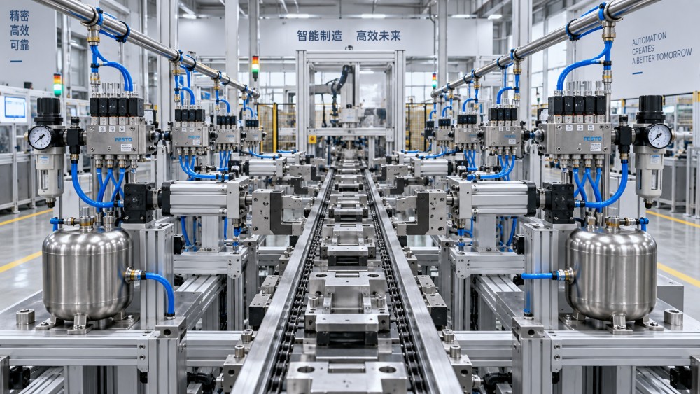
A decentralized layout divides the machine into functional zones and installs a valve island near each group of actuators. The main supply line may still run from a central air preparation point, but the final path from the valve to each cylinder is short. This is usually the preferred configuration for long transfer lines, modular automation cells, large fixtures, conveyor systems, multi-axis handling equipment, and installations where distant stations must respond in a narrow time window.
The gain is not merely lower friction loss. Shorter actuator lines reduce the compressible air volume between valve and cylinder. That improves response consistency and makes flow controls more predictable. Local valve islands can also be sized around the demand of a specific module instead of forcing one central manifold to serve unlike loads. A heavy clamp group can receive a larger supply branch, a higher-flow manifold, or local air storage without oversizing every station in the line.
Distributed control does introduce trade-offs. More islands can mean more field wiring or network nodes, more local mounting requirements, and a greater need to protect components against water, dust, vibration, welding spatter, or mechanical damage. Maintenance teams need clear zone identification and shutoff provisions. Yet these are manageable design issues. They are generally easier to solve during layout and commissioning than chronic pressure instability is to solve after the machine enters production.
The valve is only one restriction in the circuit
Valve selection should begin with required actuator behavior. Cylinder bore, stroke, operating pressure, intended cycle time, load condition, and the number of movements that overlap determine air demand. The relevant valve flow rating must then be interpreted using the manufacturer’s stated test conditions. Flow descriptions are not always presented in the same form across suppliers; nominal port size alone is a poor substitute for checking the published flow characteristic and pressure-drop relationship.
Project teams often focus on valve port threads while overlooking the smaller restrictions around them. A narrow push-in fitting, a long length of flexible tube, a compact speed controller, or a muffler with limited exhaust capacity can dominate the pressure drop. Exhaust restriction is particularly easy to miss. During cylinder retraction or extension, trapped exhaust air can create back pressure that slows motion even when incoming supply pressure appears acceptable.
For fast or large-bore cylinders, quick-exhaust arrangements located near the actuator may be evaluated where the application permits them. They can reduce the exhaust path length, but they are not a universal correction. Noise, contamination ingress, controlled motion requirements, safety behavior, and the potential effect on cushioning all require review. A faster stroke is not automatically a better stroke.
Manifold supply, local reservoirs, and regulation by zone
A well-designed valve island still depends on a stable local supply. The feed to each zone should be evaluated for its own peak flow rather than sized by a rough average across the whole line. If several large actuators in one zone extend together, that branch needs adequate pipe diameter, suitable fittings, and a regulator that can pass the required flow without a severe transient pressure drop.
Local receiver volume can help when demand arrives in short pulses. Positioned upstream of the local manifold, a properly considered reservoir supplies nearby peak flow while the upstream line catches up. It does not create air capacity by itself, and it cannot compensate for a continuously undersized compressor, leaking network, or inadequate main distribution. Its value is greatest where high demand is intermittent and cycle analysis shows a recovery period.
Zone regulation is also useful when stations need deliberately different pressures. Clamping may require one setting, gentle part handling another, and blow-off circuits another again. Separate regulators prevent a low-pressure function from forcing the entire line to operate below the level required by a critical actuator. They can also make troubleshooting clearer: pressure measured at the zone inlet, manifold supply, and cylinder port tells a much more useful story than a single gauge at the machine air inlet.
Do not solve a layout problem with higher set pressure
Raising the upstream regulator setting is a common field response to slow remote stations. It may mask the issue temporarily, but it can increase air consumption, alter actuator impact, stress seals, and create excessive force at stations that were already receiving adequate pressure. If the problem is restriction during simultaneous motion, higher source pressure does not address the underlying imbalance.
A more disciplined test is to record pressure at several points while the machine performs the troublesome sequence: after the main regulator, at the manifold inlet, at the valve outlet if practical, and close to the actuator. Compare a single-station movement with the normal simultaneous cycle. The location of the pressure change points to the restriction: upstream air generation and preparation, zone distribution, manifold capacity, downstream tubing, or exhaust.
Leaks should be addressed before major component changes. Small leaks may not explain a sharp transient drop by themselves, but an already compromised air supply leaves less margin when the line reaches peak demand. Contamination matters as well. Filter condition, condensate management, lubricant compatibility where applicable, and clean installation practices affect valve response and seal life over time.
A practical specification path for project teams
Before approving a valve layout, build a station-by-station demand map. Identify every actuator, its bore and stroke, required motion time, load-sensitive functions, normal operating pressure, and the sequence in which it moves. Then identify the maximum credible overlap. The critical condition is usually not total daily consumption; it is the short interval when multiple cylinders, grippers, air knives, or blow-off functions demand air together.
Use that map to decide whether stations should be grouped into local valve islands. Put valves close to high-flow or timing-critical actuators. Keep tube routes direct, avoid unnecessary diameter reductions, and treat silencers, check valves, couplers, and flow controls as part of the sizing exercise. Where safety functions are involved, confirm the required de-energized state, restart behavior, isolation method, and any project-specific requirements independently of the flow calculation.
For large projects, documentation should show more than a pneumatic symbol diagram. It should identify zone boundaries, supply branch sizes, regulator locations, valve manifold flow capability, tube lengths where they are consequential, actuator operating conditions, and test points for commissioning. This level of definition helps procurement compare technically equivalent offers and prevents later substitutions from quietly reducing available flow.
This is the kind of system-level review supported by Global Industrial Machining & Piping Equipment Network (IMPE). Across fluid power, piping, machining, and industrial equipment topics, the useful question is often not whether an individual component meets a catalog description, but whether materials, interfaces, tolerances, and operating conditions work together through the full project lifecycle.
The configuration decision in plain terms
If a multi-station line is physically long, contains fast or large pneumatic actuators, or has significant simultaneous movement, use decentralized Pneumatic Valves on local manifolds near the station groups. Supply each island through a branch sized for its peak demand, and consider local air storage only after confirming the demand profile. This configuration shortens the most sensitive air paths and makes pressure behavior easier to control.
A centralized manifold remains a valid choice for compact, low-demand equipment, particularly when maintenance access and environmental protection outweigh the benefit of local mounting. The decision should be verified with the full flow path, not with valve port size or compressor pressure alone. When specifications are still being developed, the most productive next step is to review the actuator schedule, simultaneous-motion sequence, available supply conditions, and acceptable pressure drop at each critical station before the tubing layout is fixed.
Related News
- How to Assess a Rigid Coupling Supplier for Bore Accuracy and Traceable QualityOct 08, 2026Tribology & Kinematics Expert
- Titanium Alloys Compared: Balancing Strength, Corrosion Resistance, and MachinabilityOct 08, 2026CNC Kinematics Architect
- Where Ductile Iron Dismantling Joints Reduce Alignment Risk in Water PipelinesOct 08, 2026Pipeline Metallurgy Scientist
- Selecting a Precision Bearing Sleeve: Fits, Runout, and Material ChoicesOct 08, 2026Tribology & Kinematics Expert
- Face Milling Cutters: How Insert Geometry Affects Finish on Steel and AluminumOct 08, 2026CNC Kinematics Architect
- Single-Acting Cylinders for Clamping: Stroke, Force, and Return Spring ConsiderationsOct 07, 2026Fluid Power Control Strategist