
What to Ask a Flow Control Valve Manufacturer Before Approving a New Supplier
The lowest quoted valve often becomes the highest-cost choice when its control range is poorly matched to the process, trim materials erode early, documentation cannot support acceptance, or replacement parts are unavailable during an outage. Approval should begin with questions that expose how a proposed flow control valve manufacturer translates an operating duty into a repeatable product, rather than how attractive its catalog appears.
Start by providing the actual service conditions: fluid composition, normal and maximum flow, upstream and downstream pressure, expected pressure drop, temperature range, solids content, viscosity, flashing or cavitation potential, pipe size, installation orientation, and required failure position. Then ask the supplier to state which conditions were used for sizing. A serious technical response identifies missing information and records assumptions. A simple valve size and pressure-class quotation does not establish that the valve will regulate well in service.
Ask How the Valve Has Been Sized, Not Only Which Size Is Offered
“Full line size” is not automatically the correct control valve size. A valve that is too large may spend most of its travel near closed position, where small stem movements create excessive flow changes. That can cause unstable control, hunting, noise, and accelerated seat wear. A valve that is too small can create excessive velocity, pressure loss, and limited maximum capacity.
Ask: What flow coefficient is required at minimum, normal, and maximum duty, and where will normal operation fall on the valve travel curve? The response should distinguish between shutoff capability and controllability. A valve may pass the required maximum flow but still deliver poor modulation at the normal operating point.
Further questions should address the selected inherent characteristic. Equal-percentage trim often suits services where the pressure drop across the valve changes substantially with system flow. Linear trim may be appropriate where valve pressure drop remains relatively constant. The correct answer depends on the installed characteristic, which includes piping losses, pump behavior, and downstream pressure changes. Request the supplier’s explanation of the assumed system behavior rather than accepting a characteristic name alone.
For water, wastewater, slurry, steam, compressed air, hydraulic oil, corrosive chemicals, or gas service, the sizing calculation needs different attention. Compressible fluids require pressure and temperature treatment that differs from liquid sizing. Slurry service raises questions about particle size, concentration, velocity, and dead zones. A clean-water reference valve is not evidence that the same design will regulate abrasive solids acceptably.
Pressure Rating Does Not Answer the Full Pressure Question
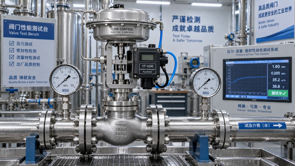
Ask for the maximum allowable working pressure of the assembled valve at the specified temperature, not merely the nominal pressure class of the body. Body material, flange rating, bolting, packing arrangement, actuator capability, and trim design can introduce separate limits. The requested shutoff pressure also deserves its own question: At what differential pressure is the stated shutoff class valid, and is that differential pressure available throughout the actuator stroke?
A pneumatic actuator may close a valve under normal differential pressure but fail to achieve the same shutoff when upstream pressure reaches a transient maximum. Spring range, air supply pressure, actuator area, friction, unbalanced trim force, and seat load all affect the answer. For electric actuation, ask about torque or thrust margin at end of travel, particularly where deposits, cold starts, or long idle periods increase breakaway force.
Pressure drop must be treated as a process condition, not as pressure “consumed” harmlessly by the valve. High liquid pressure drop can produce cavitation, flashing, vibration, and trim damage. Flashing continues downstream of the restriction and may damage pipework as well as the valve. Ask whether the supplier has evaluated these conditions and what design feature addresses them: staged pressure reduction, anti-cavitation trim, hardened components, a different valve style, or a revised installation arrangement.
Trace the Material From Body to Soft Parts
Request a complete bill of materials for the offered configuration, including body, bonnet, trim, stem, seat, plug or disc, guides, packing, gaskets, fasteners, coatings, and any elastomeric components. “Stainless steel valve” is too broad to judge corrosion resistance or mechanical suitability. A stainless body paired with an unsuitable stem, spring, seat insert, or fastener can still create a weak point.
Ask which material certificates can be supplied for pressure-retaining parts and critical trim, how heat or lot identification is maintained through machining and assembly, and whether markings link the finished valve to those records. Traceability has practical value when a chemical analysis, heat treatment record, or replacement component must be verified later. It should not end at a generic material declaration.
Material selection also needs to reflect the actual medium. Chloride-bearing water, acidic condensate, hydrocarbons, oxygen service, abrasive media, high-purity fluids, and outdoor installations create different exposure mechanisms. Internal corrosion, external atmosphere, insulation, cleaning chemicals, and stagnant periods may matter as much as the primary process fluid. Ask the supplier to identify any stated exclusions in the material recommendation.
Soft materials deserve equal scrutiny. Seat and packing selections affect leakage, friction, temperature capability, chemical resistance, and emissions performance. A soft seat can improve shutoff in clean service but may deform, swell, or erode under unsuitable temperature, pressure, or fluid conditions. A metal seat can tolerate harsher conditions but may require a different leakage expectation and more careful evaluation of particulate damage.
Examine the Manufacturing Route Behind Repeatability
Ask whether the body is cast, forged, bar-machined, fabricated, or sourced as a standard pressure component, and ask which operations are performed under the supplier’s direct control. The purpose is not to favor one route universally. Cast bodies can be suitable for many duties when foundry quality, machining allowances, and inspection are controlled. Forged or bar-machined construction may be selected where material integrity, pressure duty, geometry, or production volume warrants it.
The more revealing questions concern controls at the features that determine valve performance. How are seat bores machined and inspected? What establishes stem-to-guide alignment? Are sealing surfaces lapped, ground, coated, or machined? How is concentricity checked after assembly? How are trim components protected from mix-up when multiple alloys or characteristics are processed in the same facility?
Ask for the inspection plan tied to the order rather than a general statement that quality checks are performed. It should identify dimensional inspection, pressure testing, seat leakage testing, functional stroke verification, surface or non-destructive examination where applicable, and final visual review. If a special coating, overlay, heat treatment, or elastomer is specified, determine whether verification occurs before assembly and whether the record follows the valve serial number or batch.
Clarify What the Test Results Actually Prove
A hydrostatic shell test indicates that the pressure boundary has been tested under the stated conditions; it does not prove control accuracy, long-term cycling life, corrosion resistance, or suitability for severe cavitation. Seat leakage results require the test medium, test pressure, direction of pressure, allowable leakage criterion, and valve condition to be understood. A result obtained with clean water may not predict leakage after abrasive process exposure.
Ask the supplier to provide the proposed test sequence and sample records before order release. Useful questions include:
- Which components receive pressure testing, and is the test performed before or after actuator mounting?
- Will the valve be stroked through its full travel and checked for binding, backlash, or incorrect travel stops?
- How are fail-open, fail-close, or fail-in-place actions verified after accessories are installed?
- When positioners, solenoids, limit switches, or feedback transmitters are included, which signals and calibration points are documented?
- Can a witness or hold point be arranged for critical project valves without disrupting the production sequence?
Factory testing should match the purchased assembly. A body tested separately from the final trim, actuator, and accessories leaves unresolved questions about assembled function. Conversely, demanding elaborate tests for a straightforward noncritical service can add cost and delay without improving the acceptance decision. The required evidence should follow the consequence of failure and the difficulty of correcting defects after installation.
Review the Valve, Actuator, and Accessories as One Assembly
Flow control performance depends on the complete loop. Ask what actuator is selected, its available force or torque across the relevant travel, required supply pressure or electrical input, cycle duty, enclosure suitability, and manual override arrangement. Confirm the air quality requirements for pneumatic accessories, since moisture, oil carryover, or particulate contamination can cause erratic positioner behavior long before the valve body shows a defect.
Positioner selection should be linked to the control requirement. Ask about input signal, feedback method, travel calibration, fail action, and compatibility with the intended control architecture. A digital positioner may offer diagnostic functions, but those functions are useful only when the installation has the required wiring, air supply quality, configuration access, and maintenance capability. For simple on-off isolation combined with occasional throttling, the selected package may differ from a continuously modulating application.
Request dimensional drawings that show face-to-face length, flange details, actuator envelope, handwheel clearance, cable or air connections, and maintenance access. A technically sound valve can still create field rework when the actuator interferes with pipe supports, platforms, insulation, or adjacent equipment. For large or heavy assemblies, lifting points and center-of-gravity information should be confirmed before shipment.
Expose the Cost Assumptions Before Comparing Quotes
A quote comparison should separate base valve cost from the items that change delivered and installed cost. Ask whether the price includes actuator, positioner, air filter regulator, solenoid, switches, mounting hardware, flange studs, gaskets, special coatings, testing, certificates, spare seals, preservation, export packing, and documentation review. Apparent price gaps often come from different boundaries of supply rather than a genuine difference in valve value.
Ask whether the quoted lead time begins after receipt of order, approval of drawings, receipt of special materials, or completion of document review. This distinction becomes significant when a valve contains nonstandard trim, alloy components, special coatings, or configured instrumentation. Also establish the process for changes after approval: which changes require written authorization, how revised drawings are controlled, and whether a substitution of material, accessory, or manufacturing location is permitted without notice.
Test Technical Communication During Qualification
The approval stage is a practical test of how issues will be handled after an order is placed. Submit a realistic data sheet containing an incomplete or challenging condition and assess the response. A capable supplier will ask focused questions, explain the consequence of unknown conditions, identify conflicts between requested requirements, and issue a controlled revision when assumptions change. Generic assurances leave the technical risk unresolved.
Ask who owns the technical query from sizing through final documentation, how deviations are recorded, and how urgent field questions are handled after delivery. Confirm that serial numbers, tag numbers, drawings, test records, and spare-part references use a consistent identification system. These details become important when several similar valves arrive at one site or when an installed unit needs a replacement trim years later.
Approval is strongest when the selected configuration, evidence requirements, commercial boundary, and deviation process are captured in the purchase specification. That record turns the initial evaluation into an enforceable basis for production and acceptance, rather than relying on an interpretation of a catalog page or an informal email exchange.
Related News
- Using Industrial Air Blow Guns to Clear Chips Without Spreading DebrisOct 15, 2026Fluid Power Control Strategist
- Ductile Iron Pipe Valves: Which AWWA Standards Apply to Water Main Projects?Oct 15, 2026Dr. Elias Vance
- Why Vacuum Suction Cups Lose Grip on MDF in Woodworking MachinesOct 15, 2026CNC Kinematics Architect
- Choosing a Variable Displacement Piston Pump Manufacturer: What to VerifyOct 15, 2026Fluid Power Control Strategist
- Parallel vs. Angular Pneumatic Grippers for Confined Assembly StationsOct 15, 2026Fluid Power Control Strategist
- Die Castings vs. Investment Castings: Which Costs Less at Your Production Volume?Oct 14, 2026Foundry Phase-Change Fellow