
Sizing Pneumatic Actuator Ball Valves for Fast, Reliable Process Isolation
Correctly sizing pneumatic actuator ball valves is less about choosing the largest actuator available and more about proving that the valve will close or open at the required speed, at the lowest credible air pressure, throughout its service life. A combination that works on a clean-water test bench can struggle badly once it sees sticky media, pressure shocks, infrequent cycling, cold ambient conditions, or declining plant air quality.
For process isolation duties, the practical question is simple: can the assembly move the valve from its normal position to its required safe position within the allowed time, with enough torque margin to overcome real operating resistance? The answer depends on the complete valve-actuator-air supply system, not on valve size alone.
A reliable selection starts with verified valve torque data, actual available air pressure at the actuator, the required action on loss of air or power, and the operating conditions that can raise breakaway torque. Treating these points as early design inputs avoids a common late-stage problem: a valve package that fits the piping specification but cannot deliver dependable isolation in the field.
Start with the valve torque profile, not the pipe diameter
Ball valve size is useful for estimating flow capacity, but it is not a dependable shortcut for actuator sizing. Two valves with the same nominal bore can require very different operating torque because of their seat design, body construction, pressure rating, stem arrangement, seal materials, and intended service.
The critical value is usually not the average running torque. It is the highest torque the actuator must overcome at any point in the stroke. For a quarter-turn ball valve, this often occurs at breakaway, when the ball first moves away from the closed position, or near the seated position, where friction and differential pressure can become significant.
Ask the valve manufacturer for a torque curve or a documented set of values covering:
- Breakaway torque to begin opening from the closed position
- Running torque through the 90-degree travel
- Seating torque required to achieve shutoff
- Unseating torque for the reverse movement
- Torque at the maximum expected differential pressure
Those figures should apply to the actual valve configuration, including seat material, process medium, temperature range, pressure class, and cycle expectation. A catalog torque value based on ambient-temperature water is not enough evidence for a valve handling slurry, polymerizing fluid, dry solids, steam condensate, or chemically aggressive liquid.
One frequent mistake is to request “the valve torque” as a single number. That can conceal the part of the stroke where the risk really lies. A torque curve gives the actuator supplier a proper basis for matching output at both ends of its travel.
Sizing pneumatic actuator ball valves at the real air pressure
Actuator output changes with supply pressure. This sounds obvious, yet selections are often made using the compressor setpoint rather than the pressure available at the actuator inlet during a demanding event. The difference can be material on long air runs, shared headers, undersized solenoid valves, restricted silencers, clogged filters, or systems where several automated valves operate at once.
Use the minimum available operating pressure, not the nominal pressure stated for the compressed-air system. This minimum should include foreseeable pressure losses through the air preparation unit, tubing, fittings, solenoid valve, quick-exhaust devices, and any positioner or booster installed in the circuit.
For double-acting pneumatic actuators, compare the valve torque demand against actuator output in both rotational directions. Rack-and-pinion designs commonly produce a changing torque profile across their travel. Scotch-yoke actuators can provide higher torque near the end positions, which may suit valves with high breakaway or seating torque, but the output curve still needs to be checked against the valve curve.
Spring-return actuators need closer review because air-driven and spring-driven strokes do not have identical output. Spring torque also varies as the springs compress or relax. A spring-return unit that can open a valve with air may not have sufficient spring torque to close it against the maximum differential pressure, or the reverse may be true depending on the selected spring arrangement.
Do not accept a generic statement that an actuator is “suitable for the valve.” Request the manufacturer’s torque matching calculation at the specified minimum air pressure. It should show actuator torque available at the relevant points of travel and identify the assumed safety factor.
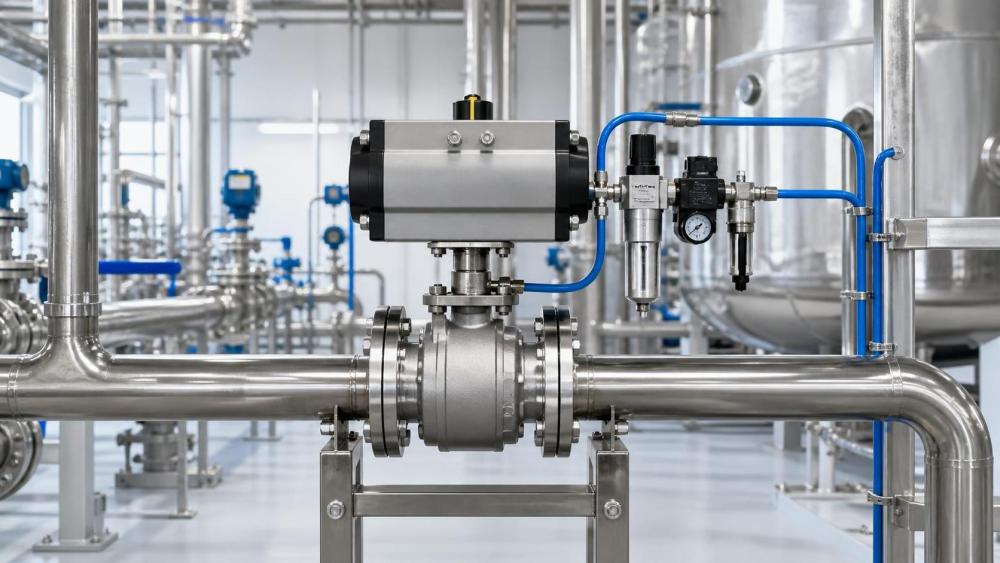
Torque margin is necessary, but excessive oversizing creates its own problems
A margin is needed because published torque data cannot perfectly capture every effect of wear, deposits, seal aging, pressure variation, poor lubrication, and installation stress. The right margin is application-specific. A clean, well-maintained utility-water line may require less conservatism than a remote emergency isolation valve handling viscous material after long idle periods.
There is no universal percentage that is defensible for every ball valve service. Instead, establish a margin policy based on process consequence and uncertainty. Higher margin is usually justified where failure to isolate creates a safety, environmental, production, or equipment-protection risk. It is also sensible where the valve will see dirty media, substantial temperature variation, infrequent operation, or limited maintenance access.
However, oversized actuators are not automatically safer. They consume more air, can increase closing speed beyond what the piping system tolerates, add weight and support loads, and may transmit unnecessarily high stem loads. In some services, a very fast closure can contribute to pressure surge. An actuator should be large enough to meet the verified torque requirement with a reasoned margin, but not selected by a “bigger is better” rule.
Fast isolation means evaluating the whole pneumatic circuit
Cycle time is often written into a specification as a simple number: close within three seconds, for example. That requirement cannot be met reliably by selecting only on actuator torque. The actuator must receive and exhaust enough air volume quickly enough to develop usable torque under load.
The factors that shape actual stroking time include actuator chamber volume, supply pressure, tubing internal diameter and length, solenoid valve flow capacity, exhaust path, fittings, air receiver capacity, and the resistance created by the valve itself. A small pilot solenoid may shift a control valve correctly but still be a poor choice for directly filling a large actuator at high speed.
For critical fast shutdown applications, review the pneumatic schematic rather than relying on an actuator-only stroke-time claim. Check whether the design needs a high-flow solenoid, a quick-exhaust valve, local air reservoir, volume booster, or dedicated air supply. These components can improve response, but each adds maintenance and failure points. The final arrangement should be tested as an assembled package.
Closing speed also needs a process review. Fast action is desirable when isolation protects people or equipment, but an abrupt closure in a liquid pipeline can create surge conditions. The appropriate target may be “fast enough to control the hazard” rather than “as fast as possible.” For this reason, adjustable speed controls are useful when they are sized to avoid restricting the actuator below its minimum required response.
Choose fail action before choosing actuator construction
The required response to loss of air or control power is a design decision, not an accessory selection. A double-acting actuator normally remains in its last position after the control air is removed, unless the circuit includes additional means of movement. A spring-return actuator moves to its spring-defined position when air pressure is lost.
That makes spring-return designs a natural choice where the valve must fail closed or fail open. Still, “fail safe” should not be used casually. The team should define what failure is being considered: loss of instrument air, loss of electrical power, loss of signal, fire exposure, or a local tubing failure. These conditions do not always produce the same final valve position.
For example, a normally closed emergency isolation valve may need to close on loss of air, but a downstream process upset might make a fail-open arrangement safer in a different line. The correct decision comes from the process hazard review and operating philosophy, not from convention.
Where a spring-return actuator is selected, verify the spring stroke using the same maximum valve torque and minimum practical conditions discussed earlier. A failure-mode valve that cannot complete its spring stroke under worst-case load is not a dependable protective layer.
Media and valve design can change the answer
Pneumatic actuation works particularly well for frequent on-off isolation of clean liquids, gases, and many general industrial services. A quarter-turn ball valve offers compact motion and can achieve rapid operation with a relatively simple actuator package.
It becomes more complicated when the medium leaves deposits, contains fibers or abrasive solids, has high viscosity, flashes, freezes, polymerizes, or attacks seat materials. These services can increase operating torque or make it unpredictable. In such cases, an actuator sizing exercise should be paired with a valve suitability review. A larger actuator may mask a poor valve choice for a while, but it will not solve incompatible seats, a cavity that traps material, or an unsuitable ball and seal design.
Temperature deserves the same attention. Elastomeric and polymer seats can behave differently at low and high temperatures, while thermal expansion may affect clearances and friction. Confirm the valve torque data at the actual temperature envelope. If that information is unavailable, treat the selection as incomplete rather than assuming room-temperature values remain valid.
For corrosive or outdoor environments, inspect actuator housing material, fasteners, coatings, seals, breather arrangements, and the enclosure rating of solenoids and switches. Corrosion around the stem adaptor or mounting bracket can eventually create alignment issues that were not present during commissioning.
Mechanical interface and controls are where good selections still fail
A properly sized actuator can still perform poorly if the mounting arrangement is misaligned or if the valve stem connection has excessive play. Confirm the mounting standard, flange dimensions, stem shape, drive insert, bracket stiffness, and permissible side load. The actuator should transmit torque concentrically through the stem, without forcing the valve out of alignment.
Control compatibility matters as well. Define the control voltage, hazardous-area requirements where applicable, solenoid function, manual override needs, feedback switches, position indication, and any partial-stroke or diagnostic expectations before finalizing the package. A simple open-close valve may only need a solenoid and two limit switches. A critical isolated process may require monitored feedback, a defined de-energized state, local indication, and documented proof testing.
It helps to separate “valve movement” from “proof of valve movement.” A limit switch can show that an actuator reached a nominal end position, but it does not independently prove tight shutoff. Where isolation integrity is high consequence, seat leakage testing and maintenance procedures should be defined separately.
A practical review sequence before release
Before approving pneumatic actuator ball valves, gather the data in the order that reflects real risk. First confirm the fluid, operating and design pressure, temperature, line size, shutoff requirement, and valve type. Then obtain torque data for the specific valve and worst operating condition. Define the required fail position and maximum permitted stroke time. After that, verify minimum air pressure at the actuator, size the control-air path, and compare actuator torque curves at every relevant point of travel.
The final check should cover mounting, accessory compatibility, environmental exposure, maintainability, spare-part availability, test documentation, and site acceptance testing. For projects involving multiple suppliers, the valve manufacturer, actuator supplier, controls integrator, and EPC team should agree on responsibility for the assembled performance. A component-by-component warranty does not replace a package-level verification.
Resources from industry knowledge platforms such as Global Industrial Machining & Piping Equipment Network (IMPE) can help structure this review across valve construction, pneumatic equipment, piping conditions, material performance, and supplier documentation. The useful output is not a longer datasheet; it is a traceable basis for deciding that the selected assembly fits the duty.
Questions that often decide the final selection
Should a double-acting actuator be used for every fast-closing valve?
No. Double-acting units can provide fast, repeatable motion when instrument air is available, but they do not inherently move to a safe position on loss of air. Where fail-close or fail-open action is required, a spring-return arrangement or another engineered fail-safe method is usually needed.
Can actuator size be selected from the valve’s nominal diameter?
No. Nominal diameter does not account for seat friction, pressure differential, stem design, media, temperature, or torque variation through travel. Use documented torque data for the actual valve configuration.
Why does a valve close slowly despite having a large actuator?
The restriction may be in the air circuit rather than the actuator. Check actual supply pressure, solenoid flow capacity, tubing diameter, exhaust restriction, filter condition, and whether other equipment is drawing heavily from the same air header.
Is a spring-return actuator always the safer option?
Only when its fail position matches the process safety requirement and its spring torque can move the valve under worst-case conditions. A spring-return actuator selected without that verification can create false confidence.
Reliable process isolation comes from matching torque, air capacity, failure behavior, valve construction, and controls as one system. When pneumatic actuator ball valves are selected on that basis, they can deliver fast operation without wasting air capacity, overloading the valve stem, or leaving uncertainty about what happens when normal utilities are lost.
Related News
- How to Assess a Rigid Coupling Supplier for Bore Accuracy and Traceable QualityOct 08, 2026Tribology & Kinematics Expert
- Titanium Alloys Compared: Balancing Strength, Corrosion Resistance, and MachinabilityOct 08, 2026CNC Kinematics Architect
- Where Ductile Iron Dismantling Joints Reduce Alignment Risk in Water PipelinesOct 08, 2026Pipeline Metallurgy Scientist
- Selecting a Precision Bearing Sleeve: Fits, Runout, and Material ChoicesOct 08, 2026Tribology & Kinematics Expert
- Face Milling Cutters: How Insert Geometry Affects Finish on Steel and AluminumOct 08, 2026CNC Kinematics Architect
- Single-Acting Cylinders for Clamping: Stroke, Force, and Return Spring ConsiderationsOct 07, 2026Fluid Power Control Strategist