
Selecting Pneumatic Actuator Valves for Water Treatment: Fail-Safe and Media Factors
At a water treatment plant, a valve rarely fails at a convenient time. It may be during a backwash sequence, a chemical dosing adjustment, a storm-driven inflow event, or a maintenance shutdown when operators need a line isolated without delay. For technical evaluators, selecting pneumatic actuator valves for water treatment is therefore not simply a matter of pairing a valve with an air cylinder. The selection determines what happens when air pressure is lost, whether the valve can tolerate the process media, and how reliably the installation will behave after thousands of cycles.
The best choice begins with the process consequence, not the valve catalogue. A butterfly valve that remains open on loss of air may be appropriate for one service line and unacceptable for another. A corrosion-resistant actuator may still be a poor solution if its seals cannot withstand chemical vapors. Likewise, a correctly sized valve can become unreliable when it is asked to throttle abrasive sludge or when available instrument air falls below the pressure assumed in the sizing calculation.
For municipal utilities, EPC teams, and equipment evaluators, the goal is to define an actuator-valve assembly that supports treatment continuity, operator safety, maintainability, and lifecycle value across raw water intake, filtration, chemical treatment, sludge processing, and distribution duties.
Start with the consequence of valve position on air failure
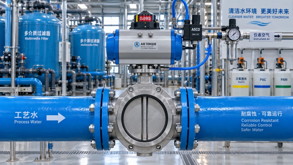
Fail-safe action is usually the first and most consequential decision. Pneumatic actuators are commonly available in double-acting and spring-return configurations. A double-acting actuator uses compressed air to drive the valve in both directions. It provides dependable torque in each stroke, but without a spring mechanism, the valve generally remains in its last position if the air supply disappears. That may be acceptable where a stable last position is safer than an automatic movement, provided the operating procedure addresses loss of air.
A spring-return actuator uses air for one direction and stored spring energy for the return stroke. It gives the system a defined response to air failure:
- Fail closed (FC): commonly selected for chemical dosing isolation, drain control, contaminated process streams, and lines where uncontrolled flow presents a safety or quality risk.
- Fail open (FO): often considered for cooling water, overflow protection, gravity drainage, or services where continued flow prevents equipment damage or hydraulic upset.
- Fail in place: typically associated with double-acting designs, used only after evaluating the impact of holding the last valve position during air or power loss.
The terms can create confusion because actuator rotation, valve mounting orientation, and valve type all affect the final result. “Spring-to-close” is not automatically equivalent to “fail closed” until the actuator is mounted on the valve and the complete assembly has been stroke-tested. Procurement documents should state the required valve flow position on loss of control air, rather than relying only on actuator terminology.
A useful review question is simple: if the instrument air compressor trips at 2 a.m., where must this valve be to protect people, water quality, equipment, and the treatment process? The answer should be agreed by process engineering, operations, and safety personnel before the actuator type is finalized.
Valve torque is not a single number
Actuator sizing is often reduced to break torque, but real water treatment duty requires a broader torque profile. The actuator must overcome seating torque, running torque, unseating torque, packing friction, and the effects of differential pressure. For resilient-seated butterfly valves, breakaway torque can rise after long periods without operation. For ball valves, seat friction and pressure-induced effects may dominate. Plug valves can require substantial torque, especially where solids, deposits, or elastomer swelling are present.
Spring-return units deserve particular attention because their output torque changes throughout the stroke. A technically sound sizing review checks whether the available spring torque is sufficient at the exact point where the valve needs maximum torque during its fail-safe stroke. It is not enough for a supplier to show a nominal actuator torque that appears higher than a published valve value.
Ask for a torque calculation that identifies valve type, size, pressure differential, operating temperature, media condition, required safety factor, and the available minimum and maximum air pressure. The calculation should also distinguish clean-water assumptions from actual service conditions. A valve installed in clarified water has a different operating reality from the same nominal valve used on dewatered sludge.
Read the media as a mechanical and chemical condition
“Water treatment” covers media with very different behavior. Clean potable water, raw water, seawater, chlorinated water, ferric chloride, lime slurry, polymer solution, activated sludge, and wastewater effluent cannot be treated as one service category. The actuator may be outside the pipe, but its valve, stem, seals, fasteners, and accessories remain exposed to the consequences of the process environment.
Clean water and filtered water
For relatively clean, non-corrosive water, butterfly valves and ball valves with pneumatic actuation are common choices for isolation and automated sequencing. Selection still depends on pressure class, water hammer potential, cycle frequency, and the internal lining or seat material. In drinking-water applications, material suitability and local regulatory expectations may also influence elastomer, coating, and lubricant choices.
Raw water, wastewater, and solids-bearing streams
Solids change the evaluation substantially. Grit, fibers, biological matter, scale, and suspended solids can accumulate around seats or interfere with closure. Full-port ball valves, knife gate valves, plug valves, and suitably designed butterfly valves may be considered depending on the line function and solids characteristics. The important point is that actuator torque must reflect the likelihood of deposits and not merely the torque of a new valve tested with clean water.
For sludge and slurry duties, valve geometry is often more important than actuator sophistication. A compact quarter-turn actuator will not compensate for a valve design that traps solids in its seat area. Evaluators should review flow path, cavity formation, flushing provisions, stem protection, and whether the valve can deliver repeatable shutoff after extended service.
Chemical dosing and aggressive media
Chemical systems require close attention to wetted materials, sealing materials, and external corrosion exposure. Sodium hypochlorite, chlorine-containing vapors, acids, alkalis, coagulants, and oxidizing chemicals may attack metals, elastomers, fasteners, or accessory housings. A chemically compatible valve body is only part of the answer; stem seals, seat compounds, diaphragms where applicable, tubing, solenoid seals, and positioner internals should be reviewed as a system.
In enclosed chemical rooms, airborne vapor can corrode actuator springs, mounting brackets, switch boxes, and stainless-steel components that would otherwise perform well in neutral service. Protective coatings, appropriate enclosure ratings, remote mounting, and thoughtful ventilation may be as valuable as a change in base material.
Air supply quality is part of actuator selection
Pneumatic actuation is valued because it can be fast, robust, and well suited to wet industrial settings. Yet the actuator is only as dependable as its air supply. Before approving a design, confirm the minimum available supply pressure at the valve location during peak demand, not simply the compressor discharge pressure. Long runs, undersized tubing, shared air headers, frozen condensate, and poorly maintained filters can reduce usable pressure at the moment a valve must stroke.
Air preparation should match the actuator manufacturer’s requirements. Dry, filtered instrument air reduces internal corrosion, sticking, and seal wear. In cold climates, moisture management is critical: condensate in tubing or solenoid valves can freeze and leave a carefully designed fail-safe function unavailable. Where the valve must move quickly during an emergency, local air reservoirs or quick-exhaust arrangements may be appropriate, but they should be evaluated alongside the risk of water hammer and abrupt hydraulic changes.
Solenoid valve selection also matters. A normally closed or normally open solenoid configuration must support the intended fail action, and its voltage, enclosure, coil duty, and manual override provisions need to fit the plant’s control philosophy. The smallest accessory can become the weak point in an otherwise capable valve package.
Match the valve and actuator to the control task
Not every automated valve is a control valve. Many pneumatic actuator valves in water treatment are intended for on/off isolation: opening a filter inlet, initiating backwash, isolating a tank, or directing flow through parallel process trains. These applications may need reliable end-position feedback and controlled stroke time, but not highly accurate intermediate positioning.
Where flow modulation is required, such as pressure control, flow control, level regulation, or chemical feed adjustment, the evaluation becomes more demanding. The valve’s inherent flow characteristic, rangeability, pressure-drop behavior, cavitation risk, and required control accuracy must be considered together with a pneumatic positioner or electro-pneumatic control package. A standard isolation butterfly valve may move to intermediate positions, but that does not automatically make it suitable for stable throttling service.
Fast closing can be equally problematic. In long distribution lines or pump discharge systems, rapid valve movement may create surge pressure. A stroke-time requirement should be based on hydraulic analysis or established operating practice, not on the assumption that faster is always safer. Speed-control valves, dampers, or staged sequencing may be needed to protect pipelines, fittings, and connected equipment.
A practical evaluation sequence for pneumatic actuator valves for water treatment
Technical teams can reduce late-stage revisions by collecting the following information before issuing a request for quotation or approving a submittal:
- Define the service: Identify the actual media, solids level, chemical concentration, temperature range, pressure, flow direction, and expected differential pressure.
- Set the process response: Document the required valve position on loss of air, loss of electrical signal, and loss of control command.
- Select the valve architecture: Choose the valve type based on isolation, throttling, solids handling, shutoff expectation, and maintenance access.
- Verify torque over the full stroke: Request valve torque data and actuator output data at the specified minimum air pressure, including spring torque where relevant.
- Review materials beyond the body: Include seats, seals, stem packing, coatings, fasteners, actuator springs, mounting hardware, tubing, and accessories.
- Confirm controls and feedback: Check solenoid arrangement, limit switches, position indication, positioner needs, enclosure conditions, and interface with the plant control system.
- Plan for serviceability: Consider manual override, lockout needs, spare seal availability, access for removal, and the ability to test the fail-safe function in the field.
Common selection mistakes that create avoidable risk
One frequent mistake is specifying “pneumatic actuator” without identifying the fail position. Another is accepting actuator sizing based on normal air pressure while the plant routinely experiences lower pressure at remote locations. A third is using clean-water torque values for valves exposed to deposits, slurry, or infrequent operation.
There is also a tendency to focus on the valve body material while overlooking the accessory package. In water treatment environments, corrosion can begin at the mounting bracket, terminal box, pneumatic tubing fitting, or solenoid exhaust port long before the primary valve body shows a problem. Evaluators should inspect the entire assembly as an installed system, including washdown, humidity, UV exposure, chemical room atmosphere, and outdoor temperature swings.
Finally, fail-safe should be tested, not assumed. Factory acceptance testing and site commissioning should verify direction of travel, end positions, feedback signals, stroke time, air consumption, manual override operation, and response to simulated loss of air or power. The test record becomes especially valuable years later, when maintenance teams need to diagnose a changed operating response.
Selection is ultimately a lifecycle decision
The right pneumatic actuator valve arrangement is one that behaves predictably under ordinary operation and under the less ordinary conditions that matter most: a compressor fault, a chemical spill, a plugged line, a high-solids batch, or an unexpected control-system interruption. This is why selection should connect process design, valve engineering, fluid compatibility, instrumentation, and maintenance planning rather than treating them as separate purchasing questions.
For technical evaluators comparing pneumatic actuator valves for water treatment, a well-structured specification is often more valuable than a long list of product options. When fail-safe intent, media exposure, torque margins, air quality, control duty, and test requirements are clear, suppliers can propose assemblies that are easier to evaluate on a like-for-like basis—and more likely to remain dependable through the operating life of the treatment system.
Related News
- How to Assess a Rigid Coupling Supplier for Bore Accuracy and Traceable QualityOct 08, 2026Tribology & Kinematics Expert
- Titanium Alloys Compared: Balancing Strength, Corrosion Resistance, and MachinabilityOct 08, 2026CNC Kinematics Architect
- Where Ductile Iron Dismantling Joints Reduce Alignment Risk in Water PipelinesOct 08, 2026Pipeline Metallurgy Scientist
- Selecting a Precision Bearing Sleeve: Fits, Runout, and Material ChoicesOct 08, 2026Tribology & Kinematics Expert
- Face Milling Cutters: How Insert Geometry Affects Finish on Steel and AluminumOct 08, 2026CNC Kinematics Architect
- Single-Acting Cylinders for Clamping: Stroke, Force, and Return Spring ConsiderationsOct 07, 2026Fluid Power Control Strategist