
Selecting Compact Valve Manifold Blocks for Space-Limited Pneumatic Automation
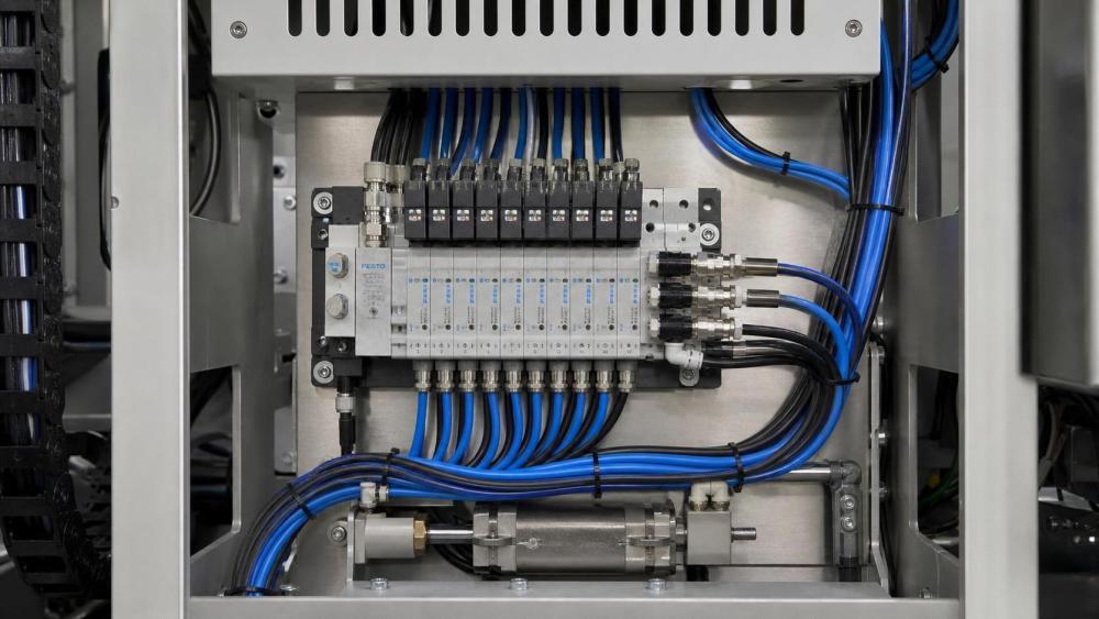
When a pneumatic control panel must fit inside a narrow machine frame, a compact valve manifold block can appear to be the obvious choice. The difficulty usually begins after installation: restricted flow paths may slow actuator movement, closely spaced ports may make tubing difficult to route, and a dense assembly may leave too little room for removing a valve or tightening a fitting. A smaller footprint does not automatically produce a better pneumatic system.
The most reliable selection method is to treat the manifold as part of the complete air circuit rather than as a simple mounting accessory. Compare the required flow, pressure, valve function, port orientation, exhaust capacity, service access, and future expansion before comparing external dimensions. A manifold that is slightly larger but easier to maintain may be the better choice for an OEM machine or an automated production cell.
Start with the installation envelope, not the catalog size
Space-limited automation often has several competing constraints. The manifold may need to fit behind a guarding panel, beside a linear actuator, inside a robot end-of-arm assembly, or within a machine cabinet that already contains sensors and electrical terminals. Measure the available volume in three dimensions and include the space needed for tubing bends, connector removal, valve replacement, and inspection.
Catalog dimensions commonly describe the body or assembled valve bank without showing the practical clearance around it. A right-angle fitting can add more width than the manifold itself. Solenoid connectors may require vertical clearance, while exhaust silencers can project into an adjacent cable channel. The usable envelope should therefore include:
- Manifold body length, width, and height;
- Valve and coil removal clearance;
- Tube bending radius and fitting access;
- Electrical connector orientation;
- Exhaust outlet and silencer space;
- Room for labeling, leakage inspection, and future service.
Draw the manifold and its connections in the same orientation used by the machine layout. This often reveals that a block with the smallest nominal width creates a deeper assembly once push-in fittings, mufflers, and cables are installed.
Flow capacity must match the actuator demand
A compact valve manifold block should not be selected only by port size. Port diameter is an important starting point, but actual pneumatic performance also depends on the valve’s internal passages, effective flow area, pressure drop, exhaust arrangement, and the length of tubing between the manifold and actuator.
Estimate the air demand from the actuator bore, stroke, cycle frequency, operating pressure, and required motion time. The manifold and valve should then be checked against the flow requirement under the expected supply and exhaust conditions. A small cylinder used for light clamping may work well with a compact low-flow valve. A large-bore cylinder moving rapidly, or several actuators operating at the same time, may need a manifold with larger internal passages and a higher flow rating.
Undersizing often produces symptoms that are mistaken for a defective cylinder. The actuator may move slowly only during simultaneous operations, fail to reach the expected speed, or show a noticeable difference between extension and retraction. Pressure measured at the regulator can look acceptable while pressure at the actuator falls during a high-demand stroke. This is why the flow specification should be evaluated at the valve and manifold assembly, not at the compressor or main air header alone.
Separate supply flow from exhaust flow
Many evaluations focus on inlet flow and overlook exhaust restriction. Exhaust air must leave the working port quickly enough to avoid back pressure. A compact manifold with a shared or undersized exhaust path can limit actuator speed even when the supply port is adequate. Check whether the design uses individual exhaust ports, common exhaust channels, or optional exhaust control. The answer affects both response time and the ability to tune separate actuators.
Speed-control requirements also influence the selection. Meter-out control is often used for stable cylinder movement, but its effectiveness depends on the exhaust path and the installed flow-control fittings. When several valves share a narrow exhaust passage, one actuator can influence another during overlapping cycles.
Choose the valve arrangement according to control logic
The manifold block is only useful when its valve configuration matches the pneumatic function. Review whether each actuator needs a 3/2, 5/2, or 5/3 valve, and confirm whether the cylinder is single-acting or double-acting. A compact assembly can reduce wiring and tubing, but an incorrect center condition or return method can create a functional risk.
For example, a 5/3 valve with a closed center may hold pressure in both cylinder chambers when the control signal is removed, while a floating or exhaust center produces a different result. The appropriate choice depends on the machine sequence, load behavior, stopping requirements, and the consequences of air loss. Do not assume that a smaller valve bank can be substituted without reviewing the sequence diagram.
Consider these arrangement details during comparison:
- Number of valve stations required at initial commissioning;
- Whether unused stations can be blanked safely;
- Single-solenoid or double-solenoid operation;
- Manual override type and access direction;
- Individual or common supply and exhaust paths;
- Electrical interface, polarity, and connector clearance;
- Availability of spare stations or modular expansion.
A manifold with one more station than the immediate requirement may reduce future redesign, but extra volume is not always justified. In a very confined assembly, adding unused positions can obstruct maintenance or increase dead volume. The decision should be based on a realistic expansion plan rather than a general preference for spare capacity.
Port orientation can decide whether the design is serviceable
Two manifolds with identical flow ratings may behave very differently once installed. Port orientation determines how tubes cross, where fittings can be reached, and whether the assembly can be removed without disconnecting unrelated circuits. Side ports may suit a shallow cabinet, while top ports may be better when the manifold is mounted against a backplate.
Keep working lines as short and direct as the layout permits, but do not force tight bends to save a few millimeters. Excessive bending can stress fittings, increase leakage risk, and make replacement difficult. If the machine contains moving axes, route tubing so that its motion, abrasion, and minimum bend radius remain within the tubing manufacturer’s limits.
Label the valve stations and both actuator lines before final installation. A dense valve bank can make troubleshooting slow when identical tubes are grouped closely together. Clear identification is particularly useful when a maintenance technician must isolate one actuator without disturbing the others.
Material, sealing, and air quality are selection filters
Compact manifold bodies are commonly manufactured from aluminum, engineered polymer, stainless steel, or other corrosion-resistant materials. The correct choice depends on the environment rather than on weight alone. A clean indoor assembly may favor a lightweight body, while washdown exposure, chemical contact, high humidity, or abrasive dust may require a more resistant construction and protected connectors.
Seal compatibility should be checked against the air preparation system, lubricant, cleaning agents, and operating temperature. Pneumatic systems can experience seal swelling, hardening, or leakage when an incompatible lubricant or solvent enters the circuit. If the machine uses special gases or nonstandard media, confirm compatibility separately; a manifold designed for ordinary compressed air should not be assumed suitable for every gas.
Air cleanliness has a direct effect on a compact valve assembly. Small internal passages and close-fitting spools can be more sensitive to particles, condensed water, and excessive oil than a large, simple directional valve. The selection should therefore be reviewed together with filtration, drainage, regulator location, and the quality of the plant air. A manifold cannot compensate for contaminated or unstable supply air.
Response time and control stability need practical review
Fast pneumatic automation depends on more than a high nominal flow number. Valve actuation time, manifold volume, tubing length, exhaust restriction, solenoid voltage stability, and actuator load all contribute to the actual response. A compact manifold can reduce tubing volume and improve response, but only if its internal passages are not overly restrictive.
Compare the required cycle sequence with the valve’s switching behavior. High-speed indexing may require quick exhaust or a dedicated exhaust arrangement. A gripping application may prioritize controlled pressure buildup and stable holding rather than maximum switching speed. If the valves are controlled by a PLC or remote I/O, verify the output capacity and electrical timing as well as the pneumatic timing.
Do not evaluate response using an unloaded cylinder alone. Load friction, vertical mass, cushioning adjustment, and external guides can change the result substantially. For design approval, use the expected actuator, tubing length, pressure range, and operating sequence. If the application is safety-related, the manifold’s normal switching function should also be distinguished from any required safety-rated isolation or dump function.
Compare compact manifold options by trade-off
A practical selection sequence for technical review
- Define the pneumatic functions. List every actuator, valve type, required state during signal loss, and any simultaneous movements.
- Calculate or estimate demand. Use bore, stroke, cycle rate, working pressure, target speed, and tubing length to establish the necessary flow range.
- Map the physical envelope. Include connectors, fittings, exhaust silencers, tube bends, mounting hardware, and removal clearance.
- Review the air circuit. Check supply and exhaust capacity, pressure-drop behavior, filtration, drainage, and the effect of shared passages.
- Check environmental compatibility. Confirm body material, seal material, temperature range, moisture exposure, cleaning method, and electrical protection.
- Test service access. Confirm that valve replacement, manual override operation, leak detection, and tube disconnection are possible after installation.
- Document future needs. Decide whether expansion, spare stations, alternative valve functions, or communication interfaces are actually required.
The final comparison should use the assembled configuration rather than an isolated manifold body. Request dimensional drawings, port and thread details, flow data, pressure limits, wiring information, seal specifications, and mounting requirements. When supplier data uses different flow-rating conventions, compare the test conditions before treating the numbers as equivalent.
Common selection mistakes that create later rework
Choosing the smallest available block is one of the most frequent errors. It may fit the drawing while failing to provide enough room for tools or enough flow for concurrent actuator movement. Another mistake is selecting a valve bank by the number of stations without checking the common supply and exhaust capacity. The station count can look sufficient even though the shared passages limit the whole assembly.
Ignoring cable and tubing direction creates a similar problem. A manifold may technically fit inside the enclosure but force connectors against a wall or require tubes to bend sharply around a moving component. Selecting a valve by rated pressure alone is also incomplete; the operating flow, switching function, temperature, seal compatibility, and failure position remain relevant.
Finally, avoid treating serviceability as an afterthought. Pneumatic leaks are easier to locate when lines are labeled and fittings remain visible. Replaceable valve cartridges, accessible fasteners, and clear station identification can reduce downtime without increasing the control logic complexity. The best compact arrangement is not the one with the fewest cubic centimeters; it is the one that meets the machine’s performance requirements while preserving a workable path for installation and maintenance.
Related News
- How to Assess a Rigid Coupling Supplier for Bore Accuracy and Traceable QualityOct 08, 2026Tribology & Kinematics Expert
- Titanium Alloys Compared: Balancing Strength, Corrosion Resistance, and MachinabilityOct 08, 2026CNC Kinematics Architect
- Where Ductile Iron Dismantling Joints Reduce Alignment Risk in Water PipelinesOct 08, 2026Pipeline Metallurgy Scientist
- Selecting a Precision Bearing Sleeve: Fits, Runout, and Material ChoicesOct 08, 2026Tribology & Kinematics Expert
- Face Milling Cutters: How Insert Geometry Affects Finish on Steel and AluminumOct 08, 2026CNC Kinematics Architect
- Single-Acting Cylinders for Clamping: Stroke, Force, and Return Spring ConsiderationsOct 07, 2026Fluid Power Control Strategist