
Pneumatic Valves Explained: Types, Working Principles, and Common Industrial Uses
Pneumatic valves sit at the center of many automated systems, yet they are often treated like simple on-off parts. That is where confusion starts. In practice, pneumatic valves decide how compressed air moves, when an actuator responds, how fast a cylinder extends, and whether a machine behaves smoothly or unpredictably. If you are trying to understand pneumatic valves before comparing products, reviewing a design, or discussing options with a supplier, the key is to separate three things: valve type, valve function, and operating conditions.
A short answer first: pneumatic valves are devices that control the direction, pressure, or flow of compressed air in a pneumatic system. Different valves do different jobs. Some start or stop airflow, some switch air paths, some regulate speed, and some protect the system from overpressure. Knowing that difference makes the rest much easier.
What pneumatic valves actually do in a working system
Many people assume a pneumatic system is mostly about the compressor and cylinder. In reality, the valve layout often has more influence on control quality than the actuator itself. A cylinder may be strong enough and the air supply may be adequate, but if the valve logic is wrong, the motion will still be jerky, delayed, or unstable.
Pneumatic valves manage compressed air in four basic ways:
- They start or stop airflow.
- They change the direction of airflow.
- They control pressure levels.
- They meter flow to influence speed and timing.
That sounds straightforward, but industrial applications quickly add complexity. A packaging line may need very fast switching. A dust-prone workshop may need valves with better contamination tolerance. A process plant may care more about reliability and maintenance access than switching speed. The valve is never just a catalog item; it is part of a control strategy.
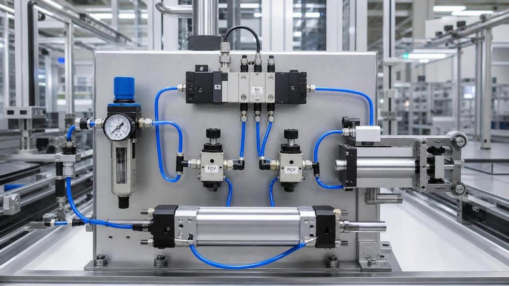
Main types of Pneumatic Valves
The easiest way to understand pneumatic valves is to group them by what they control.
Directional control valves
These are the most common. They route compressed air from one port to another so an actuator can extend, retract, hold, or exhaust. You will often see them described by port and position, such as 2/2, 3/2, 4/2, or 5/2 valves.
For example, a 3/2 valve is common in single-acting cylinder circuits, where air pressure moves the actuator one way and a spring returns it. A 5/2 valve is widely used with double-acting cylinders because it alternates air supply between two actuator ports. A 5/3 valve adds a center position, which can be useful when a machine needs a defined neutral state.
This is one of the first places new buyers get lost. The “5/2” or “3/2” label is not a quality grade. It simply tells you how many ports and switching positions the valve has.
Flow control valves
These valves regulate how much air passes through a line. In many machines, they are used to control cylinder speed. A common example is a needle-type flow control valve with a check function, allowing free flow in one direction and restricted flow in the other.
That matters because pneumatic speed control is usually more stable when exhaust air is metered rather than supply air. People new to pneumatics often overlook this and then wonder why actuator motion becomes inconsistent under changing loads.
Pressure control valves
These valves keep air pressure within a desired range. The group includes pressure regulators, relief valves, and sequence valves. A regulator maintains downstream pressure. A relief valve protects the system by venting if pressure rises too high. A sequence valve allows one action to occur only after a preset pressure is reached.
In practical terms, pressure control valves help balance force, safety, and repeatability. Too much pressure can damage components or create harsh motion. Too little pressure may leave the actuator unable to complete its stroke.
Check valves and quick exhaust valves
Check valves allow air to move in one direction only. They are simple but important for preventing reverse flow and protecting parts of a circuit.
Quick exhaust valves are used when faster actuator movement is needed. Instead of forcing exhaust air to travel back through the main directional valve, they release it close to the actuator. On high-cycle equipment, that can make a noticeable difference in response time.
How pneumatic valves work
At a basic level, a pneumatic valve works by moving an internal element such as a spool, poppet, or diaphragm. That movement opens, closes, or redirects air passages inside the valve body.
The actuation method can vary:
- Manual actuation by lever, push button, or pedal
- Mechanical actuation by cam or roller
- Electrical actuation through a solenoid
- Pneumatic pilot actuation using air pressure
Solenoid-operated pneumatic valves are especially common in industrial automation because they allow an electrical control signal from a PLC or controller to switch airflow quickly. But “solenoid valve” does not describe the whole valve function. It only describes how the valve is actuated. A solenoid valve may still be 3/2, 5/2, normally closed, normally open, single-solenoid, or double-solenoid.
That distinction matters during specification. One of the most common mistakes in early-stage sourcing is asking for a “solenoid valve” without defining the flow path, pressure range, voltage, port size, response requirement, or mounting style.
Where they are commonly used
Pneumatic valves appear in a wide range of equipment because compressed air is clean, fast, and comparatively easy to distribute. You will see them in factory automation, pick-and-place systems, conveyors, machine tools, food packaging equipment, textile machinery, material handling units, industrial presses, and many utility air circuits.
They are also common in sectors that IMPE covers closely, including fluid power systems, heavy equipment support systems, and industrial manufacturing lines where actuators, control valves, fittings, and machined components need to work as one reliable assembly.
In a packaging machine, a directional valve may trigger clamping and release cycles hundreds or thousands of times per shift. In a machining fixture, a pressure regulator and directional valve may control clamping force so the workpiece is held consistently. In material handling, flow control valves help prevent abrupt cylinder motion that can damage products or create safety concerns.
The point is not that pneumatic valves are used everywhere. It is that each use case emphasizes a different performance priority: speed, durability, cleanliness, control precision, or serviceability.
What experienced buyers check before choosing a valve
If you are still in the research phase, this is usually the most useful part.
People often compare pneumatic valves by port size first. That is understandable, but incomplete. Port size alone tells you very little about how the valve will behave in a real system. A better starting list looks like this:
- Valve function: directional, flow, pressure, check, exhaust
- Operating pressure range
- Flow capacity matched to actuator demand
- Actuation method and available control signal
- Response speed and switching frequency
- Media quality requirements, including filtration and lubrication
- Mounting format, manifold compatibility, and maintenance access
- Seal material compatibility with temperature and environment
A valve that looks acceptable on paper can still perform poorly if the compressed air quality is bad. Dirt, moisture, oil carryover, and rust particles remain common causes of sticking, leakage, and shortened service life. In many field problems, the valve is blamed first, but the real issue is upstream air preparation.
Another thing worth checking is failure mode. In some applications, a normally closed valve is preferred so air stops during power loss. In others, a different fail position is safer for the machine sequence. This is not just an engineering detail; it affects maintenance safety and process recovery.
Misunderstandings that lead to bad decisions
One frequent misconception is that higher pressure always means better performance. It does not. Higher pressure increases force, but it can also increase wear, shock loads, air consumption, and noise. The target should be the pressure needed for reliable function, not the highest available line pressure.
Another misunderstanding is treating all pneumatic valves as interchangeable if the threads match. Thread size, valve coefficient, internal design, coil rating, duty cycle, and sealing materials all influence whether the replacement will actually work.
There is also a tendency to focus only on the valve and ignore the rest of the circuit. A well-selected valve cannot compensate for undersized tubing, poor regulator stability, contaminated air, or an actuator that was wrongly chosen in the first place.
When pneumatic valves are a good fit, and when they are not
Pneumatic valves make sense when fast repetitive motion, simple automation, clean actuation, and moderate force control are needed. They are often preferred where compressed air infrastructure already exists and where maintenance teams are comfortable with fluid power systems.
They are less suitable when the application requires very high force density, very precise closed-loop motion control, or operation in environments where compressed air supply is unstable or costly. In those cases, hydraulic or electric solutions may be more appropriate.
That is why early comparison work should look beyond the valve itself. The better question is not “Which pneumatic valve is best?” but “Is a pneumatic valve the right control method for this duty?”
A practical way to evaluate pneumatic valves
If you need to move from basic understanding to actual selection, start with the machine task. Identify what has to move, how often, how fast, and under what load. Then confirm air supply quality, available pressure, control voltage, and installation constraints. Only after that does valve type selection become straightforward.
For buyers and engineers reviewing multiple equipment categories, structured technical platforms such as IMPE can be useful because pneumatic valves rarely stand alone. They connect to actuators, fittings, machined housings, manifolds, piping elements, and maintenance requirements. Looking at the valve in isolation may be enough for a replacement purchase, but not for project-level decisions.
Good valve selection usually comes down to matching function to system reality. That sounds simple, but it is where most avoidable mistakes happen.
FAQ
Are pneumatic valves and solenoid valves the same thing?
Not exactly. A pneumatic valve controls compressed air. A solenoid valve is a valve actuated electrically by a solenoid. Many pneumatic valves are solenoid-operated, but the terms are not identical.
How do I know whether I need a 3/2 or 5/2 valve?
It depends mainly on the actuator. A 3/2 valve is common for single-acting cylinders. A 5/2 valve is common for double-acting cylinders that need air supplied to two sides alternately.
Why does a pneumatic cylinder move too fast or too hard?
The usual causes are excessive pressure, poor flow control setup, or missing exhaust metering. The valve may be fine, but the circuit tuning may be wrong.
Can I replace a pneumatic valve with any valve of the same size?
No. Matching thread size is not enough. You also need to verify valve function, pressure range, flow capacity, voltage, response behavior, and seal compatibility.
Image Placeholder Notes
- : Place near the section explaining valve types. Suggested image: labeled diagram showing directional, flow control, pressure control, check, and quick exhaust valves in a basic pneumatic circuit. Alt text: “Common pneumatic valve types and their position in a compressed air system.”
Internal Link Anchor Text Suggestions
- How pneumatic cylinders work: guide page on actuator basics
- Solenoid valve selection for industrial automation: application-focused selection article
- Compressed air preparation units explained: filter regulator lubricator overview
- Hydraulic vs pneumatic systems: comparison page for fluid power choices
- Industrial control valves and flow regulation: broader valve category page
External Source Suggestions
- Industrial fluid power association technical guides
- Manufacturer official pneumatic valve catalogs and engineering manuals
- International standards and safety guidance related to pneumatic systems and machine control
For anyone researching Pneumatic Valves, the useful takeaway is this: learn the job the valve is performing before comparing models. Once you know whether the valve must switch direction, regulate flow, control pressure, or speed exhaust, the rest of the selection process becomes much more practical and much less confusing.
Related News
- How to Assess a Rigid Coupling Supplier for Bore Accuracy and Traceable QualityOct 08, 2026Tribology & Kinematics Expert
- Titanium Alloys Compared: Balancing Strength, Corrosion Resistance, and MachinabilityOct 08, 2026CNC Kinematics Architect
- Where Ductile Iron Dismantling Joints Reduce Alignment Risk in Water PipelinesOct 08, 2026Pipeline Metallurgy Scientist
- Selecting a Precision Bearing Sleeve: Fits, Runout, and Material ChoicesOct 08, 2026Tribology & Kinematics Expert
- Face Milling Cutters: How Insert Geometry Affects Finish on Steel and AluminumOct 08, 2026CNC Kinematics Architect
- Single-Acting Cylinders for Clamping: Stroke, Force, and Return Spring ConsiderationsOct 07, 2026Fluid Power Control Strategist