
How High-Pressure Valve Manifold Blocks Prevent Leakage at Critical Port Interfaces
Leakage at a high-pressure port interface rarely begins as a dramatic failure. It often starts as a thin fluid film around a cartridge valve, a fitting shoulder, or a threaded connection, then develops into pressure loss, contamination, component damage, or an unsafe external release. High-pressure valve manifold blocks prevent this progression by controlling the geometry and condition of every surface that carries pressure across an interface. Their performance is determined by the relationship between port design, machining accuracy, sealing method, material behavior, assembly load, and the pressure cycle of the hydraulic circuit.
A manifold block replaces multiple external pipes, adapters, and joints with internal drilled passages. Reducing the number of connections reduces potential leak paths, but the block itself must be machined and assembled with greater discipline. Each port is a pressure boundary. A small defect in a thread root, spotface, seal groove, cross-drilled passage, or valve cavity can create a route for fluid to escape or migrate between circuits.
Leak prevention begins with the port interface, not the pressure rating alone
A stated pressure rating indicates that a block design has a defined operating envelope, yet it does not confirm that every installed connection will seal reliably. Pressure capacity depends on the weakest local condition: the wall remaining around a port, the engagement length of the thread, the compression of the seal, the flatness of the mating face, and the strength retained by the material after machining.
Different port systems seal through different mechanisms. A tapered thread develops sealing contact along the thread flanks, often with a suitable thread sealant. A straight thread commonly depends on an elastomeric seal at a controlled face, chamfer, or counterbore. A flange connection transfers clamp load through bolts and uses an O-ring or gasket at a defined sealing land. Cartridge valve cavities rely on specified bore diameters, chamfers, and seal locations. Treating these interfaces as interchangeable is a frequent source of leakage.
A thread that appears tight can still leak when it is expected to perform a function assigned to an O-ring, bonded seal, cone seat, or flange face. Conversely, excessive tightening intended to stop a leak can deform a port mouth, damage the sealing washer, stretch fasteners beyond their intended range, or crack a relatively thin section around the connection.
Port geometry controls where pressure is allowed to act
Proper geometry gives pressurized fluid no direct route past the intended seal. The sealing area must be concentric with the mating component, free from burrs, and supported by enough material to resist local distortion. This is especially important where a port intersects an internal cross-drilled passage. The intersection may be hidden after installation, but its location affects wall thickness, stress concentration, debris removal, and the integrity of the sealing region.
Blind drilled passages require reliable control of drill-point depth and plug arrangement. If the remaining material at the end of a blind hole is too thin, pressure cycling can flex the wall. If a cross bore breaks into a threaded region or an O-ring groove, the seal may bridge an interruption rather than sit on continuous metal. Fluid can then track beneath the seal despite correct assembly torque.
Seal grooves and counterbores deserve the same scrutiny as the nominal port diameter. Groove width, depth, corner radii, lead-in chamfers, and surface condition govern seal compression and extrusion resistance. A groove that is too shallow over-compresses an O-ring, raising assembly damage and compression-set risk. A groove that is too deep permits insufficient contact stress. A sharp entry edge can shave the seal during installation, leaving a defect that may not become visible until the circuit reaches pressure.
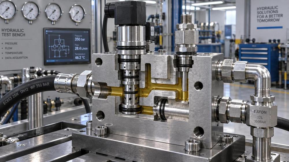
Interfaces that look similar can fail for different reasons
A leak at the top of a fitting may indicate a damaged washer or an uneven sealing face. Fluid emerging from the threaded area can indicate incompatible thread form, poor thread engagement, inadequate sealant application, or a crack extending from the port. Leakage around a cartridge valve may be caused by an incorrect cavity, a nicked installation seal, contamination in the bore, or excessive bore roughness. These failure modes should not be grouped simply as “loose connections.”
The location of visible oil is also not always the origin of the leak. Pressurized fluid can travel along threads, under a retaining feature, through a casting discontinuity, or across the outer surface of the block before collecting at a lower point. Cleaning, drying, staged pressurization, and close observation are more useful than retightening every nearby connection.
Machining quality creates the sealing surface
High-pressure valve manifold blocks are often machined from steel, stainless steel, aluminum alloy, or ductile iron selected for the fluid, pressure range, weight target, corrosion exposure, and required service life. Material selection cannot be separated from machining. A material with suitable bulk strength may still present a poor interface if machining leaves torn metal, burrs, chatter marks, embedded abrasive particles, or localized surface damage.
Surface finish must match the sealing method. A static O-ring needs a smooth, continuous surface that allows controlled deformation without providing a spiral leakage path. A face-sealing washer requires an adequately flat and perpendicular bearing surface. Threaded interfaces need clean, correctly formed flanks; polishing a thread indiscriminately does not correct pitch, taper, or form errors. Excessively rough surfaces can abrade elastomers and create microchannels. Extremely smooth surfaces are not automatically better when the seal design requires a particular finish range to retain lubricant or maintain stable contact.
Tool wear matters because port features are often produced in sequence: drilling, reaming, tapping, spotfacing, boring, and deburring. A worn tap can alter thread quality without making the error obvious in a basic visual inspection. A dull drill may leave a burr at an internal intersection. An unstable boring operation can create taper or lobing in a cartridge cavity. Inspection should therefore examine the feature that seals, rather than relying only on the external appearance of the completed block.
Dimensional controls need to reflect the actual mechanism of sealing. For a cartridge cavity, the critical dimensions may include bore diameter, depth to the shoulder, concentricity between related diameters, and the finish at O-ring travel zones. For a face-seal port, flatness and perpendicularity may matter more than the outside diameter of the spotface. For a threaded port, gauge acceptance, thread depth, lead chamfer, and local wall thickness must be considered together.
Material strength and wall thickness protect the interface under load
Pressure creates hoop and radial stresses around each drilled passage. These stresses become more severe near closely spaced ports, large cavities, sharp internal transitions, and plugged cross holes. The block may withstand static pressure while still suffering fatigue damage under repeated loading if geometry concentrates stress around a port.
Port spacing is therefore a structural issue as well as a layout issue. Moving two ports closer together may shorten a compact manifold, but it reduces the ligament of material between them. Deep threads, large counterbores, and oversized plugs can remove more material than a surface drawing suggests. A sound design reviews the remaining wall around every pressure passage, especially where ports meet at angles or where a valve cavity sits near an external mounting face.
Material condition also affects stability. Residual stress, inconsistent heat treatment, inclusions, or porosity can become relevant when a heavily loaded sealing region is machined near the surface. Cast blocks require suitable attention to internal soundness and machinability; forged or bar-stock blocks require attention to grain direction, material condition, and the effect of machining on local section thickness. Material documentation is useful only when it corresponds to the actual block material and its traceable production route.
Thread selection must match the sealing principle
Threads are commonly mistaken for the seal itself. In many high-pressure assemblies, their primary function is to generate and retain clamp load. The seal is formed elsewhere. A straight-thread connection with an O-ring at the face should not be substituted with a tapered-thread fitting simply because the nominal size appears compatible. Pitch, thread angle, taper, sealing position, and installation depth all change.
Where tapered threads are specified, the thread form and engagement depth must be controlled. Insufficient engagement leaves inadequate contact area and poor mechanical support. Excessive engagement can split the port, bottom the fitting, or force the fitting beyond its intended orientation. Sealant should fill minor helical leakage paths without masking damaged threads or compensating for incompatible components. Applying too much sealant introduces another risk: excess material can enter a hydraulic passage and obstruct an orifice, valve seat, or pilot circuit.
Where a straight thread uses an elastomeric seal, the counterface must be clean and correctly located. Rotating a fitting after the seal has been compressed can twist or cut it. Reusing a deformed washer or flattened O-ring may produce an apparently dry assembly during low-pressure testing but fail after thermal cycling or vibration.
Seal compatibility changes with fluid, temperature, and motion
An O-ring designation alone does not establish suitability. The elastomer must remain compatible with the hydraulic fluid, expected temperature range, cleaning agents, and any transient pressure conditions. Swelling, hardening, softening, or shrinkage changes the seal’s contact force and extrusion resistance. A seal that works in a mineral-oil circuit may be unsuitable in another fluid chemistry.
Pressure spikes require particular attention because they can force a seal into clearance gaps that appear harmless under steady pressure. Backup rings, anti-extrusion features, and tighter controlled clearances may be necessary where peak pressure, rapid directional changes, or pulsation are present. The need for these measures depends on the port configuration and seal type, not simply on the nominal operating pressure.
External temperature changes add another layer. A steel block and an elastomeric seal expand at different rates. A connection that is appropriately compressed at assembly temperature can change condition in service. This is one reason why seal material, groove geometry, and temperature exposure should be assessed as a set.
Assembly damage often defeats an otherwise correct design
Cleanliness is part of sealing performance. Chips trapped under a washer, fibers from a cloth, dried thread sealant, or a small burr on the port edge can produce a local gap. Hydraulic systems are particularly sensitive because debris that does not cause an immediate external leak may later reach a valve spool, nozzle, or precision clearance.
Installation torque must be applied to the component and interface specified by the connection design. Torque is only an indirect indicator of clamp load; friction from coatings, lubrication, surface condition, or reused parts can alter the resulting compression. A published torque value cannot correct a damaged port or an incorrect fitting. When a connection has a defined installation depth, orientation requirement, or backup ring direction, those details need to be retained in the assembly instruction rather than left to visual judgment.
- Protect machined ports with clean caps until final assembly so threads, seal lands, and cavities are not damaged during handling or transport.
- Remove internal burrs and flush machining debris before valves, plugs, and fittings are installed.
- Use the specified seal material and verify that the seal is seated without rolling, pinching, or cutting.
- Record pressure-test conditions, including the fluid used, test sequence, hold period, and the interfaces inspected.
Testing should distinguish proof of containment from service reliability
A pressure test confirms that the assembled block contains fluid under the selected test condition. It does not automatically reproduce cyclic loading, vibration, thermal changes, fitting side-load, or contamination exposure. A useful test sequence begins with low pressure to identify assembly leaks, then increases pressure in controlled stages while examining all external interfaces. Pressure decay, visible seepage, and migration between adjacent circuits should each be evaluated because they point to different defects.
Functional testing is also needed when the manifold contains directional, pressure-control, or proportional valves. Internal leakage through a valve is different from external leakage at a port, yet a malfunctioning valve can raise local pressure or create pressure spikes that expose a marginal seal. Circuit behavior, valve setting, and the manifold’s pressure-path design should therefore be reviewed together.
After testing, ports and cavities should be protected again. A correctly machined manifold can be compromised by impact on a sealing face, moisture trapped in an open passage, or uncontrolled contamination before installation. Packaging is part of preserving the finished interface, especially when blocks are shipped separately from the valves and fittings that will later complete the assembly.
Reliable sealing comes from preserving a continuous, correctly loaded boundary around the fluid path. Port geometry defines that boundary; machining creates it; material supports it; seals and threads close it; assembly and testing verify it. When those conditions align, the manifold block limits both external escape and unintended internal communication between high-pressure circuits.
Related News
- How to Assess a Rigid Coupling Supplier for Bore Accuracy and Traceable QualityOct 08, 2026Tribology & Kinematics Expert
- Titanium Alloys Compared: Balancing Strength, Corrosion Resistance, and MachinabilityOct 08, 2026CNC Kinematics Architect
- Where Ductile Iron Dismantling Joints Reduce Alignment Risk in Water PipelinesOct 08, 2026Pipeline Metallurgy Scientist
- Selecting a Precision Bearing Sleeve: Fits, Runout, and Material ChoicesOct 08, 2026Tribology & Kinematics Expert
- Face Milling Cutters: How Insert Geometry Affects Finish on Steel and AluminumOct 08, 2026CNC Kinematics Architect
- Single-Acting Cylinders for Clamping: Stroke, Force, and Return Spring ConsiderationsOct 07, 2026Fluid Power Control Strategist