
When Do Pressure Intensifiers Provide a Better Alternative to Larger Pumps?
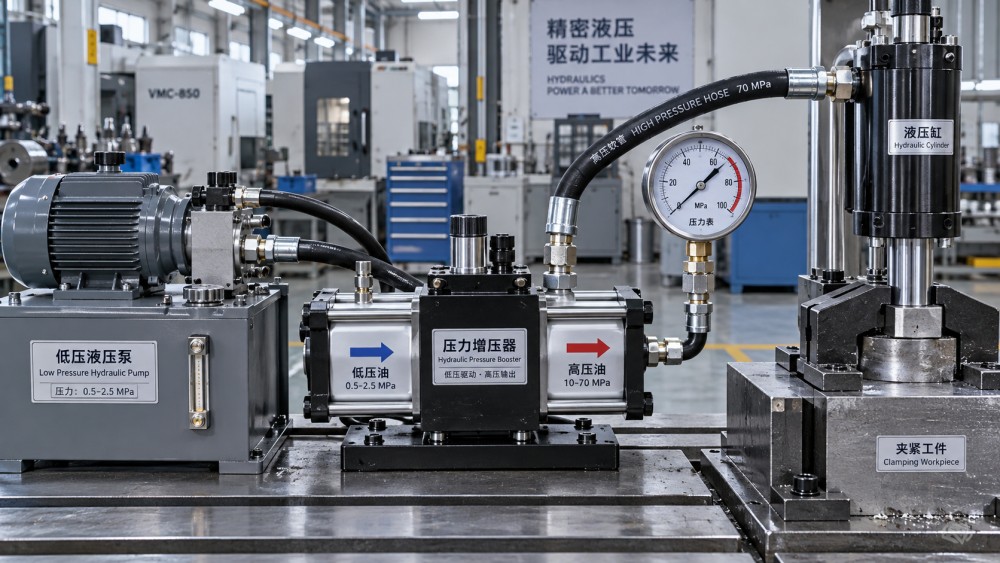
A pressure intensifier is the better alternative to a larger hydraulic pump when the system needs a limited amount of high-pressure fluid at a specific point, rather than high flow at elevated pressure throughout the entire circuit. It is particularly effective where a machine already has an adequate low- or medium-pressure supply and the higher pressure is needed only for a short clamp stroke, a localized forming operation, bolt tensioning, testing, rescue tooling, or another intermittent function.
The distinction matters because pressure and flow serve different purposes. A larger pump can raise pressure capability for the whole system, but its added displacement, drive power, heat load, and cost may be unnecessary if only one actuator or tool needs the pressure increase. An intensifier converts an available inlet flow into a smaller outlet flow at a higher pressure. The tradeoff is fundamental: pressure rises, while usable outlet flow falls in roughly inverse proportion to the intensification ratio.
That tradeoff makes an intensifier a targeted solution, not a universal replacement for pump capacity.
Start with the high-pressure demand profile
The first question is not simply, “What pressure is required?” It is, “How much fluid must be delivered at that pressure, how quickly, and for how long?” A cylinder that needs high pressure only after it contacts a workpiece has a very different demand profile from a hydraulic motor that must continuously deliver torque under high pressure.
An intensifier is well suited when the high-pressure stage involves a small volume. Consider a clamping cylinder that advances rapidly at ordinary system pressure, reaches the part, then requires a brief high-force holding phase. Using an intensifier only after contact avoids sizing the main pump and valves for the final high-pressure condition. The same logic applies to a press that requires rapid approach, followed by a low-speed high-force forming segment with modest fluid volume.
It becomes less attractive when the high-pressure function consumes substantial oil volume or must run continuously. A high-pressure motor, a large-bore cylinder moving through a long loaded stroke, or multiple simultaneous high-pressure functions will expose the intensifier's reduced outlet flow. Cycle time can become unacceptable even though the pressure rating appears adequate on a data sheet.
Pressure ratio does not create extra hydraulic power
Pressure intensification is often misread as a way to obtain high pressure without a corresponding energy consequence. The output pressure may be several times the inlet pressure, but the output flow decreases as pressure rises. Friction, internal leakage, valve losses, and fluid compression further reduce the usable output. The drive motor and primary pump still supply the energy, unless the intensifier is powered by a separate source such as compressed air.
For a hydraulic intensifier, the basic relationship is set by the effective piston areas. If the large drive piston has several times the area of the small high-pressure piston, the outlet pressure rises by approximately that ratio, less losses. The outlet flow is reduced by a similar relationship. Actual sizing must use the supplier's displacement, efficiency, and cycling data rather than an ideal ratio alone.
This has a direct effect on actuator timing. A small high-pressure cylinder chamber may fill quickly even with reduced intensifier flow. A large chamber may not. Estimating the required oil volume from cylinder bore, rod diameter, and working stroke is therefore more useful than comparing nominal pump flow with a pressure target. Include hose volume, manifold cavities, filter housings, and any accumulator charging volume; at high pressure, fluid compression and expansion can noticeably affect response.
Where an intensifier changes the system economics
A larger pump affects more than the pump itself. Raising system pressure can require a different prime mover, stronger pump mounting, higher-rated relief valves, control valves, hoses, fittings, manifolds, seals, filters, and cylinder components. It may also force changes to a power unit's tank design, cooling capacity, electrical controls, and pressure-test procedure. If the entire machine truly needs the higher pressure, those changes are appropriate. If only one compact branch needs it, they can be disproportionate.
An intensifier allows the low-pressure side to remain near its established operating range while a smaller, clearly defined high-pressure zone is built around the tool or actuator that needs it. This arrangement is often useful in retrofit work where the existing power unit has enough flow for general movement but cannot support a higher main-system pressure without broad redesign.
Compactness can also favor an intensifier. A localized unit near the point of use may eliminate the need to distribute high-pressure oil through a long machine frame. Shorter high-pressure lines reduce fluid volume and can improve response. They also simplify containment of the elevated-pressure circuit. However, placing the unit close to a hot process, vibration source, or contamination source can shorten seal life and complicate service access. Location must balance line volume against thermal and mechanical exposure.
Pressure stability separates holding applications from motion applications
Many intensifiers operate in a reciprocating cycle: they build outlet pressure, shift internally, and repeat as demand continues. That behavior may be entirely acceptable for a clamping or test circuit with a check valve and a small, controlled leakage rate. It can be unsuitable where pressure must remain extremely smooth while an actuator moves, a proportional valve meters force, or a hydraulic motor needs stable torque.
A pressure gauge may show that the target pressure is reached while concealing pressure ripple, short recovery periods, or repeated cycling at the intensifier. These effects can influence force consistency, surface quality in a forming operation, valve behavior, and fatigue loading in connected components. A larger pump or a properly controlled variable-displacement pump generally provides a more direct basis for sustained high-flow, stable-pressure service.
An accumulator can reduce pulsation and provide short peak flow, but it is not a cure for an undersized source. Its usable volume between maximum and minimum allowable pressure must cover the actual event, and its precharge must suit the service. If the accumulator repeatedly masks slow intensifier recovery, the next cycle may begin before pressure is restored. This is a common source of inconsistent clamp force or delayed actuation.
Heat and efficiency deserve an explicit comparison
Choosing a larger pump solely to meet a brief pressure peak can waste energy when the system spends most of its time unloaded or throttling excess flow. In that situation, an intensifier can reduce the amount of fluid subjected to the high-pressure condition. Yet intensifiers also generate heat through internal friction, leakage, repeated compression, and throttling at the control elements around them.
The relevant comparison is the complete duty cycle. Measure or estimate inlet pressure, inlet flow during intensification, outlet flow, time at high pressure, unload periods, and ambient temperature. A unit that runs only briefly can tolerate a thermal pattern that would be unacceptable in continuous service. Conversely, rapid repeated cycles can overheat a compact intensifier even when each individual high-pressure event is short.
Oil temperature affects viscosity, leakage, seal behavior, and lubricity. A design that performs well with cool, clean hydraulic oil may lose pressure recovery speed as the oil warms and thins. A high-pressure leak that is insignificant at one temperature can become a meaningful heat source during a long production run. Thermal assessment should therefore use the expected stabilized operating condition, not only a short bench test.
Component ratings must follow the intensified pressure boundary
The intensified section begins at the outlet of the unit and includes every connected item that can see trapped or commanded high pressure: hose assemblies, tube, fittings, manifolds, gauges, pressure switches, transducers, cylinder ports, seals, quick couplings, test connections, and isolation valves. The pressure rating of the main circuit does not automatically apply to this branch.
Particular care is needed with pressure relief strategy. A low-pressure main relief valve protects the supply circuit but may not protect the intensified outlet. The high-pressure side needs a suitably rated relief path, with adequate flow capacity for the fault being considered. A blocked outlet, failed sequencing valve, thermal expansion of trapped fluid, or malfunctioning control element can expose the branch to pressure above the intended working value.
Pressure transducers and gauges require the same scrutiny. Their normal measuring range, overload capacity, pressure port design, and response to pulsation are separate issues. A gauge that reads the expected value during commissioning can still be poorly suited to repetitive pressure spikes. Snubbers or dampers can protect instruments from pulsation, but excessive damping can hide a fast pressure excursion that matters to the machine.
Materials, seals, and fluid cleanliness
High pressure increases the sensitivity of clearances and sealing surfaces. Seal extrusion, scoring, microleakage, and contamination damage become more consequential. The elastomer must be compatible with the hydraulic fluid and expected temperature. Backup rings, surface finish at sealing bores, and extrusion gaps should match the elevated pressure condition. A cylinder designed for moderate pressure may have adequate force capacity on paper while its seals, ports, gland, or rod-end construction limit practical intensified service.
Fluid cleanliness is not merely a general maintenance issue here. Fine contamination can damage small valve clearances and check-valve seats, causing pressure decay or erratic cycling. Water contamination can reduce lubricity and promote corrosion at precision surfaces. Before adding an intensifier to an existing circuit, review the filtration arrangement, reservoir condition, return-line routing, and whether the device requires a specific inlet cleanliness level. A clogged filter indicator, unstable inlet pressure, or aerated oil should be corrected before attributing performance problems to the intensifier.
Installation details that change the result
The inlet line must provide sufficient flow without excessive restriction. Starvation or inlet pressure collapse can cause slow cycling, noise, cavitation-related damage, and unreliable outlet pressure. The return path must also be sized for the device's internal flow arrangement. Installation instructions often specify orientation, drain requirements, pilot connections, and mounting conditions because trapped air and poor drainage can alter operation.
Air is especially problematic in a high-pressure branch. Entrained air compresses, stores energy, delays pressure rise, and produces a spring-like response that can be mistaken for inadequate pump capacity. Bleeding points should be placed at high locations in the circuit, and commissioning should include repeated low-load strokes before final pressure is applied. Long flexible hoses expand under pressure as well; their expansion consumes volume and can soften response in a small-volume circuit.
Noise and vibration may also be overlooked. A reciprocating intensifier can transmit pulsation into tubing, brackets, and nearby instrument lines. Secure pipe clamps, appropriate hose routing, and a rigid mounting surface reduce fatigue risks. Do not use rigid tubing to compensate for an installation that requires movement or thermal displacement; localized bending stress is often revealed only after many pressure cycles.
Situations where a larger pump remains the sounder choice
A larger or differently controlled pump is usually preferable when high pressure and substantial flow are both required as normal operating conditions. Examples include continuous press motion under load, high-torque hydraulic motor service, multiple cylinders working simultaneously at high force, and systems where pressure recovery must be nearly instantaneous after every cycle. In these conditions, the intensifier's low output flow and cyclic behavior become core constraints rather than manageable tradeoffs.
The same conclusion applies when pressure control must be highly dynamic. Servo-hydraulic or tightly regulated proportional circuits often need predictable flow response across changing loads. Adding an intensifier can introduce delay, ripple, and nonlinear behavior that make tuning harder. A correctly selected variable-displacement pump, pressure-compensated pump, or dedicated high-pressure power unit may produce a simpler control problem and a more stable process.
There is also a maintenance boundary. An intensifier is not automatically lower-maintenance because it is smaller. A device that cycles frequently at high ratio may have demanding seal, check-valve, and contamination-control requirements. Where the main machine already needs a pump overhaul or capacity upgrade, adding a separate intensifier branch can preserve an inefficient or unreliable base system instead of solving the underlying limitation.
A useful selection calculation before specifying hardware
Define the required force, then convert it to pressure using the actuator's effective area for the loaded direction. Determine the high-pressure oil volume from the actual portion of travel under load, not the full stroke unless the full stroke is loaded. Set the allowable time for that volume to be delivered. These values establish the minimum outlet flow and reveal whether the intended intensification ratio can meet the cycle requirement.
Next, confirm the inlet pressure available during the event rather than the pressure observed at idle. Account for simultaneous machine functions, pressure losses through directional valves and filters, and expected oil temperature. Then assess outlet pressure stability, recovery time between cycles, relief protection, hose expansion, and every component rating in the high-pressure branch. A pressure intensifier is a strong alternative to a larger pump when this evaluation shows a small, intermittent high-pressure demand that can accept reduced flow and controlled pulsation without overstressing the surrounding circuit.
Related News
- How to Assess a Rigid Coupling Supplier for Bore Accuracy and Traceable QualityOct 08, 2026Tribology & Kinematics Expert
- Titanium Alloys Compared: Balancing Strength, Corrosion Resistance, and MachinabilityOct 08, 2026CNC Kinematics Architect
- Where Ductile Iron Dismantling Joints Reduce Alignment Risk in Water PipelinesOct 08, 2026Pipeline Metallurgy Scientist
- Selecting a Precision Bearing Sleeve: Fits, Runout, and Material ChoicesOct 08, 2026Tribology & Kinematics Expert
- Face Milling Cutters: How Insert Geometry Affects Finish on Steel and AluminumOct 08, 2026CNC Kinematics Architect
- Single-Acting Cylinders for Clamping: Stroke, Force, and Return Spring ConsiderationsOct 07, 2026Fluid Power Control Strategist