
What Should Buyers Verify When Comparing Hydraulic Accumulator Manufacturers?
The lowest quotation can become the highest-cost option when the vessel is undersized, the gas-side components are unsuitable, test records are incomplete, or replacement parts cannot be matched later. A hydraulic accumulator manufacturer should therefore be compared against the actual pressure cycle, fluid, temperature range, mounting arrangement, required documentation, and service life of the hydraulic circuit. Catalog capacity and maximum working pressure are starting points; they do not establish whether the unit will deliver usable oil volume, survive cycling, or fit safely into the machine.
A sound comparison begins by converting the application into a clear technical request. This should state the required fluid volume, minimum and maximum system pressure, expected cycle frequency, allowable pressure drop, ambient and fluid temperatures, fluid type, contamination conditions, installation orientation, connection details, and any governing project specifications. Without those inputs, suppliers can quote nominally similar products that perform very differently once installed.
Compare usable fluid volume rather than shell volume
Accumulator capacity is often misunderstood because the marked gas volume is not the same as the oil volume available to the circuit. The usable volume changes with precharge pressure, minimum operating pressure, maximum operating pressure, and the compression behavior of the gas. A large shell with an unsuitable precharge setting can provide less effective fluid than a smaller unit selected around the real pressure window.
Ask for the sizing basis, including the assumed precharge, gas law or duty-cycle assumption, and the calculated delivered volume between the stated pressure limits. This exposes an important difference between a quotation prepared from a nominal model number and one prepared from application data. It also reveals whether the quoted unit retains a reasonable gas cushion at the low-pressure end. Operating too close to full expansion or full compression can shorten bladder life, affect response, and increase the chance of mechanical damage inside the vessel.
For emergency energy storage, the pressure decay after pump loss matters more than average flow. For pulsation damping, the frequency and amplitude of pressure ripple matter more than a broad capacity figure. For thermal expansion compensation, fluid volume change and the interval between pressure-relief events define the requirement. These duties should not be treated as interchangeable merely because each uses a pressure vessel containing gas.
Select the internal design around the duty
Bladder, piston, and diaphragm designs each have practical boundaries. A bladder design is often valued for rapid response and relatively simple gas-side service, but repeated deep cycling, incorrect precharge, or unsuitable fluid compatibility can damage the elastomer. A piston design separates gas and fluid with a moving barrier, which can suit larger volumes or applications where controlled separation is needed; however, seal friction, orientation limits, and low-speed stick-slip behavior deserve attention. Diaphragm designs are compact and commonly used for smaller capacities, yet their usable fluid volume and repairability may differ from larger serviceable units.
The comparison should identify the exact design offered, not merely the product family. Confirm whether the bladder, piston seals, poppet, gas valve, and fluid-side components are replaceable. A repairable construction has little value if the required parts have no defined identification method or if the vessel must be returned for ordinary service. Conversely, a sealed compact design may be entirely appropriate when the duty is low volume and replacement is simpler than field maintenance.
Elastomer selection needs the same level of scrutiny. Nitrile, fluorocarbon, ethylene-propylene, and other compounds differ in compatibility with mineral oil, water-based fluids, synthetic fluids, temperature exposure, and additives. A general statement that a unit is “oil compatible” does not settle the issue when the system uses fire-resistant fluid, biodegradable fluid, unusual cleaning media, or elevated-temperature oil. Request the stated compatible fluid family, temperature limits for the specific seal compound, and any restrictions relating to gas permeability or chemical attack.
Pressure ratings need context, not a single number
Maximum working pressure must be matched to the circuit's real pressure envelope, including relief-valve setting, transient spikes, start-up conditions, and pressure intensification in connected actuator circuits. A unit rated at the normal running pressure may offer insufficient margin if short peaks occur during directional-valve shifts, load changes, or pump compensation events. The supplier should distinguish the allowable working pressure from factory test pressure and any pressure used during proof testing. Those values are not interchangeable.
Also verify the gas-side charging range and the minimum permissible precharge. An accumulator may be physically rated for the required oil-side pressure yet be unsuitable for the intended precharge relationship. Precharge is not a one-time commissioning detail: temperature variation, gas permeation, valve leakage, and maintenance practice all influence delivered performance over time.
Connection rating and port geometry can become overlooked failure points. Confirm thread form, sealing method, port material, torque limits, adapter requirements, and whether the selected fitting preserves adequate flow area. A reduced-bore adapter can make a correctly sized accumulator respond too slowly during a short-demand event. Unsupported piping can also transfer vibration and bending load into the port, particularly on mobile equipment or power units with rigid tube runs.
Trace material and pressure-boundary manufacturing
The vessel is a pressure-retaining component, so the relevant evidence extends beyond a material description in a brochure. Compare material certificates, heat or batch traceability, forming or machining controls, welding records where applicable, heat treatment records, and final dimensional verification. The depth of documentation should match the project requirement and consequence of failure.
Material selection should be linked to the operating environment. Carbon steel may be suitable in a protected indoor hydraulic power unit, while marine exposure, washdown, corrosive atmosphere, or outdoor installation can change the need for coating, stainless construction, or added corrosion protection. External paint is not a substitute for understanding base material, surface preparation, thread protection, and the corrosion path created by trapped moisture around clamps or brackets.
For forged or machined pressure shells, ask how critical bores, threads, sealing surfaces, and gas ports are controlled. A smooth-looking exterior does not show whether internal surfaces are free from machining damage, burrs, or contamination that could affect seals. Where welding is part of the construction, the scope of weld inspection and qualification should be visible in the supplied records rather than assumed from the product type.
Review test evidence at the right level
A declaration that units are “tested” is too broad to compare suppliers. The useful question is which tests apply to the offered configuration, how results are recorded, and whether the records can be tied to a serial number or production batch. Pressure testing, leak testing, functional checks, cleanliness controls, and final inspection each address different failure modes.
Testing scope should also be aligned with the purchase condition. A sample qualification result does not automatically prove that every delivered unit receives the same final verification. When documentation is required at shipment, specify the document list, identification format, language needs, and review point before production begins. Adding those requirements after units are packed often causes delay or produces records that cannot be reconstructed cleanly.
Confirm certification claims against the destination and installation
Certification should be evaluated as a document and product-configuration question, not as a logo on a data sheet. Pressure equipment requirements can vary with destination, vessel size, pressure level, application, and installation responsibility. Request the exact compliance documents applicable to the quoted model, pressure rating, material, and intended destination. A certificate covering a similar series, different capacity, or another market should not be treated as proof for the delivered assembly.
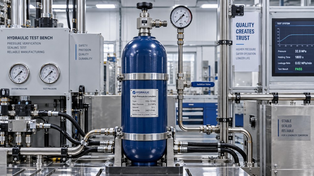
The nameplate deserves careful review. It should provide durable identification of the model, serial or batch reference where required, allowable pressure information, and other markings needed for installation and future inspection. Confirm whether labels remain legible after exposure to oil, weather, cleaning agents, and handling. Missing or ambiguous identification complicates maintenance and makes it harder to verify whether a replacement unit preserves the original design basis.
Look beyond the vessel to the installed assembly
An accumulator often arrives with brackets, safety blocks, isolation valves, gauges, charging equipment, adapters, or protective guards. These accessories can determine whether the assembly is safe to isolate, depressurize, inspect, and replace. A low unit price can lose its advantage when mounting hardware, compatible charging connections, or correctly rated isolation components are added later as separate purchases.
Verify the mounting arrangement and mass in the charged condition. Large vertical vessels require reliable support, while mobile machinery needs restraint against shock and vibration. The chosen location should allow gas precharge checks, protect the shell from impact, and avoid heat sources that distort precharge pressure. Installation drawings should show clearances for service tools as well as the normal operating envelope of adjacent equipment.
Gas charging details require particular care. Confirm the gas type specified for the design, valve interface, charging kit compatibility, and whether a protective cap is supplied. Workshop air or oxygen must not be assumed acceptable charging media. The supplied instructions should define the depressurization sequence before removal, the correct precharge measurement condition, and the precautions needed to prevent a trapped hydraulic pressure hazard.
Price comparison should include replacement and delay exposure
Quoted price becomes meaningful only after normalizing the scope. Compare delivered capacity at the required pressure window, pressure rating, shell material, seal compound, ports, accessories, documents, packing, inspection requirements, and warranty terms. A quote that omits mounts, test records, special coating, gas valves, or export packing is not directly comparable with one that includes them.
Lead time should be separated into standard model availability, configured-unit assembly, documentation review, inspection hold points, and transport readiness. A supplier that can dispatch a basic unit quickly may still require a longer period for the material, coating, certificates, or third-party inspection associated with the actual order. Confirm the process for technical changes after order release, especially changes to port threads, seal compounds, marking, or documentation. Small configuration changes can affect both delivery and compliance.
Spare-part continuity is a lifecycle issue rather than a convenience item. Record the exact model code, precharge range, bladder or seal kit reference, port details, and nameplate information in the equipment file. Before placing a repeat order, verify whether the design has changed and whether replacement parts remain compatible with units already installed. This avoids mixing visually similar components with different elastomers, pressure limits, or valve arrangements.
Use technical communication as a comparison signal
The quality of pre-order technical responses often predicts the quality of later support. Useful responses address the stated duty, identify missing inputs, explain assumptions behind sizing, and distinguish standard availability from custom configuration. Vague assurances are less useful than a drawing, data sheet revision, bill of supplied accessories, and documented acceptance criteria.
Before release, resolve conflicts between the purchase order, drawing, data sheet, nameplate requirement, test documentation, and packing instructions. The final selection should form a consistent package: a correctly sized accumulator, suitable materials and seals, verified pressure capability, traceable test evidence, compatible installation hardware, and a service path that remains workable after commissioning.
Related News
- How to Assess a Rigid Coupling Supplier for Bore Accuracy and Traceable QualityOct 08, 2026Tribology & Kinematics Expert
- Titanium Alloys Compared: Balancing Strength, Corrosion Resistance, and MachinabilityOct 08, 2026CNC Kinematics Architect
- Where Ductile Iron Dismantling Joints Reduce Alignment Risk in Water PipelinesOct 08, 2026Pipeline Metallurgy Scientist
- Selecting a Precision Bearing Sleeve: Fits, Runout, and Material ChoicesOct 08, 2026Tribology & Kinematics Expert
- Face Milling Cutters: How Insert Geometry Affects Finish on Steel and AluminumOct 08, 2026CNC Kinematics Architect
- Single-Acting Cylinders for Clamping: Stroke, Force, and Return Spring ConsiderationsOct 07, 2026Fluid Power Control Strategist