
Selecting a Hydraulic Pressure Intensifier for Clamping and Test Fixtures
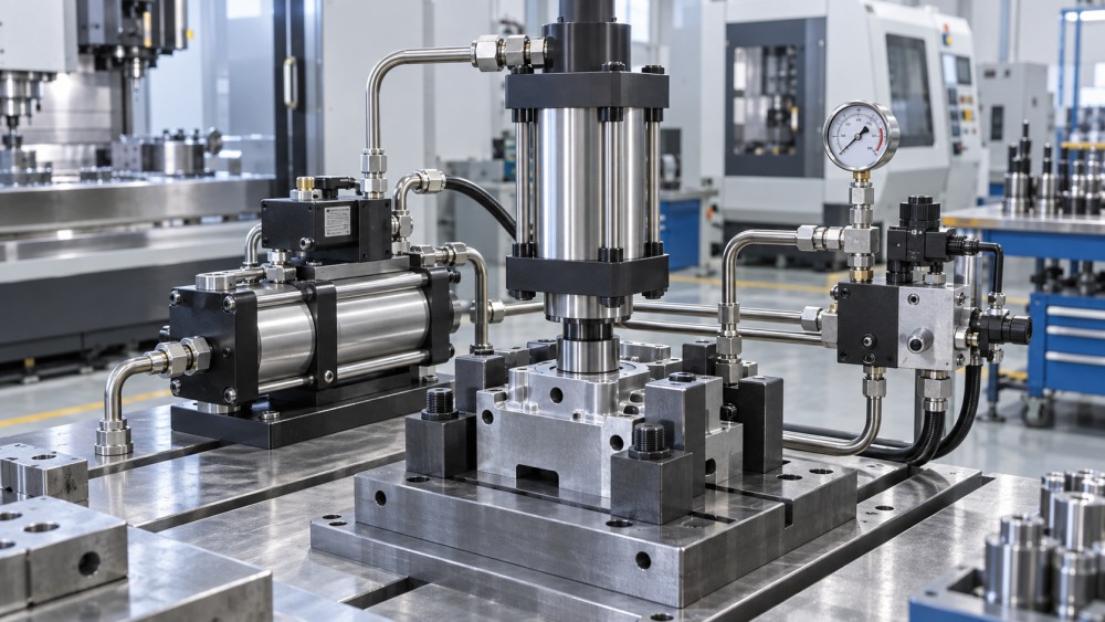
A hydraulic pressure intensifier is a good fit for a clamping or test fixture when the existing hydraulic supply provides adequate flow but not enough pressure at the point where force is needed. It can create a high-pressure branch for a compact clamping cylinder, workholding element, or proof-test circuit without requiring the entire hydraulic power unit to operate at that higher pressure.
That distinction matters. The correct selection is not simply the unit with the highest pressure ratio. A poorly matched intensifier can create slow clamp cycles, unstable holding force, excess heat, seal failures, or a fixture that cannot release safely after a pressure fault. The first task is to define the force, stroke, cycle, and safety behavior required at the fixture, then select an intensifier around those conditions.
Start with the required force at the clamp or test point
Pressure is only one part of the clamping equation. The fixture must generate enough usable force to resist machining loads, part movement, vibration, internal test pressure, or fixture distortion. That force is determined by the effective area of the hydraulic cylinder or clamp element as well as the available pressure.
For a machining fixture, the required force should account for cutting direction, changing tool engagement, part geometry, friction at the locating surfaces, and the possibility of interrupted cuts. A clamp that holds a part during a light finishing pass may not provide enough margin for heavy milling, drilling, or machining a forged or cast component with variable stock allowance.
For a test fixture, the load may come from internal pressure acting on a sealed area, from a component trying to separate at a joint, or from a test adapter that must remain compressed to prevent leakage. In these applications, fixture stiffness is as important as the nominal force. Increasing pressure will not correct a flexible frame, poorly supported adapter, or seal arrangement that extrudes under load.
Once the required force is understood, select the cylinder bore and intensifier output pressure as a pair. Using a small cylinder with very high pressure may save space, but it also raises demands on hoses, fittings, valves, seals, and the fixture body. A slightly larger actuator working at a more moderate pressure can be the more durable solution where space permits.
Choose a pressure ratio that matches the available supply
A hydraulic pressure intensifier increases output pressure by using a larger low-pressure piston to drive a smaller high-pressure piston. The pressure ratio expresses the relationship between inlet and outlet pressure. In practical terms, inlet pressure multiplied by the ratio gives an approximate no-load output pressure, subject to internal losses and the unit's operating limits.
The ratio must be selected from the actual minimum supply pressure, not the nominal setting on the hydraulic power unit. Pressure can fall when other fixture functions move, when a pump unloads, when a long supply line creates losses, or when several stations are actuated together. If the system only reaches the desired high pressure under ideal conditions, clamp force will vary from cycle to cycle.
A high ratio is useful when inlet pressure is restricted, but it brings tradeoffs. The high-pressure side receives less fluid volume for a given inlet flow, so the final pressurization stage may be slower. Higher output pressure also increases sensitivity to leakage, contamination, pressure spikes, and component rating errors. Select the lowest ratio that reliably achieves the required working pressure with a reasonable operating margin.
Separate approach speed from final clamping pressure
Many clamping fixtures do not need high pressure while the cylinder is moving through most of its stroke. They need fast, low-force approach to bring the clamp into contact, followed by a controlled high-pressure phase to lock the workpiece. Treating these as separate duties is often the most efficient way to use an intensifier.
A typical arrangement allows the main hydraulic supply to fill the cylinder quickly. Once the clamp contacts the workpiece or reaches a defined position, the high-pressure branch takes over and the hydraulic booster raises pressure in a smaller trapped volume. This reduces cycle time compared with forcing all cylinder volume through the intensifier. It also limits high-pressure exposure to the part of the circuit that needs it.
For test fixtures, the same principle may apply to seating a seal or closing a test cover. Low pressure can position the tooling, while intensified pressure establishes the final sealing load. However, the circuit must be designed so that the pressure transition does not shock the component under test or create a sudden movement that damages seals, sensors, or lightweight adapters.
Where the application requires a long stroke under full load, an intensifier may be less suitable than a higher-pressure power unit, a larger cylinder, or a redesigned clamping geometry. An intensifier is most effective when it supplies high pressure to a limited volume rather than acting as the sole source for continuous high-flow motion.
Verify flow, cycle frequency, and heat before finalizing the layout
Intensifiers are sometimes specified from pressure alone, then found to be too slow once installed. The output side receives a reduced flow relative to the inlet side because of the pressure multiplication process. The time required to build final pressure depends on the oil volume downstream, internal leakage, hose expansion, and the rate at which the intensifier cycles.
For a fixture with one small clamp, this may have little effect. For multi-clamp fixtures, large-bore cylinders, or stations expected to run frequent automated cycles, it can become a production constraint. The intensifier may cycle repeatedly to replace small losses, creating heat and unnecessary wear even while the fixture is meant to be holding steady.
Calculate the high-pressure fluid volume for the actual section of the circuit. Include cylinders, manifolds, hoses, gauges, test adapters, and any accumulators. Then consider the number of simultaneous clamps, the expected operating sequence, and whether several fixtures share a hydraulic supply. The required answer is not merely “can the intensifier reach the pressure?” but “can it reach and maintain that pressure within the available cycle time?”
Continuous or near-continuous high-pressure demand usually calls for a different hydraulic architecture. A pressure intensifier is generally a localized force solution, not a substitute for properly sized pump capacity in a sustained high-duty system.
Design the high-pressure circuit as a complete assembly
The intensified branch must be treated as a high-pressure system from the intensifier outlet to the final actuator. A common error is to upgrade the booster while leaving a gauge, quick coupling, fitting, flexible hose, or compact manifold rated only for the base system pressure. The weakest downstream component determines the safe limit of the installation.
Pressure relief is equally important. The circuit needs a controlled way to limit excessive output pressure and to release trapped pressure during maintenance, fixture changeover, or fault recovery. An intensifier can continue building pressure if its inlet remains available and the outlet is blocked. The pressure-control strategy must therefore reflect the actual circuit behavior, not only the nameplate rating of the intensifier.
Check-valve placement deserves careful review. Check valves can help retain clamping pressure, but they can also trap pressure where it prevents safe unclamping or makes a fixture appear depressurized when a loaded chamber remains isolated. Include a deliberate release path, clearly defined valve positions, and a method to verify that pressure has been relieved before service work begins.
For test fixtures, pressure monitoring may serve two different purposes: confirming fixture holding pressure and measuring the pressure applied to the test article. These should not automatically be assumed to be the same value. A restriction, isolation valve, or changing seal load can create a difference between them. Use separate measurement points when the distinction affects test validity or fixture protection.
Leakage, seals, and fluid cleanliness determine holding stability
High pressure magnifies problems that may be barely visible in a conventional hydraulic circuit. Internal leakage across a valve or cylinder seal can cause a clamp to relax over time. External leakage creates safety and housekeeping issues, while air entrainment makes pressure response less predictable and can produce a spongy clamping feel.
Seal compatibility must be reviewed against the hydraulic fluid, temperature range, expected pressure, and motion pattern. A seal that works well in an intermittent low-pressure cylinder may wear rapidly when exposed to intensified pressure, side loading, or frequent cycling. The same review applies to test-fixture seals, especially where a component surface has machining marks, casting texture, or inconsistent geometry.
Contamination control is not a maintenance detail to postpone until commissioning. Small particles can damage the close-clearance surfaces and check valves that allow an intensifier to work. They can also keep a valve partly open, allowing pressure decay that appears to be an unexplained fixture problem. Specify filtration and flushing practices appropriate to the hydraulic components used, and keep temporary installation debris out of the high-pressure branch.
Match the control method to the fixture's failure behavior
The choice of manual, pneumatic, electrical, or machine-controlled actuation changes more than convenience. It determines how the fixture reacts to power loss, emergency stop conditions, incomplete clamp travel, and an interrupted production cycle.
In a manually loaded machining fixture, a simple valve sequence with visible pressure indication may be appropriate. In an automated cell, the control system may need confirmation that clamps have reached position and that pressure has achieved a stable threshold before machining begins. Position sensing alone is not enough when a clamp can reach its end position without generating adequate holding force.
Test fixtures often require an interlock that prevents the test cycle from starting until the cover, adapter, or restraint system is fully clamped. The release sequence should also consider residual internal test pressure. Releasing fixture force before the test article is safely depressurized can turn a routine test into a hazardous separation event.
Do not assume that pressure retention is always the preferred response to lost power. In some applications, holding the clamp is safer; in others, controlled release is necessary to avoid trapping a part, fixture, or test article in an unsafe condition. The correct choice depends on the process, stored energy, access to the fixture, and the consequences of an unexpected stop.
Installation constraints often decide between similar models
Mounting space, hose routing, ambient temperature, vibration, access for inspection, and noise can make a technically suitable intensifier impractical. A compact unit placed inside a fixture may shorten high-pressure lines and reduce pressure loss, but it can also make maintenance difficult. A remotely mounted unit can be easier to service, though longer lines add oil volume, response delay, and more potential leak points.
Review the unit with the full fixture layout, not as a standalone catalog item. Confirm mounting orientation, port access, allowable load on connections, drain or vent needs, and room to replace seals or service valves. For equipment exposed to coolant, chips, washdown, dust, or outdoor conditions, protect the hydraulic assembly without making it inaccessible.
Documentation should be part of the selection package. The fixture drawing should identify the maximum intensified pressure, pressure-controlled components, relief path, gauge locations, service isolation points, and expected clamp sequence. This is especially valuable when the fixture will be maintained by a different team than the one that designed it.
A practical specification sequence
- Define the required holding or test restraint force at each critical point, including realistic load direction and reasonable process variation.
- Select actuator size and clamp geometry before using pressure multiplication to compensate for an undersized fixture.
- Establish the minimum available inlet pressure and the fluid volume that must reach high pressure.
- Choose a pressure ratio that reaches the target output pressure without relying on ideal supply conditions.
- Confirm final pressurization time, recovery time between cycles, and expected duty level.
- Rate every component in the intensified branch for the maximum pressure that can occur, including hoses, gauges, valves, fittings, and fixture passages.
- Define relief, release, pressure monitoring, and machine interlock behavior before fabrication begins.
- Plan inspection access, filtration, commissioning checks, and replacement parts for the fixture's operating environment.
Global Industrial Machining & Piping Equipment Network (IMPE) treats hydraulic selection as part of the wider fixture and equipment decision, where machining tolerance, component materials, fluid control, inspection needs, and serviceability all affect final performance. That perspective is useful because an intensifier rarely fails a project by itself; problems usually arise at the interfaces between the pressure source, fixture mechanics, control logic, and maintenance plan.
The most reliable specification is therefore a balanced one: enough pressure to create the required force, enough flow for the real cycle, a high-pressure circuit rated as a complete system, and a release strategy that remains predictable when the normal sequence is interrupted.
Related News
- How to Assess a Rigid Coupling Supplier for Bore Accuracy and Traceable QualityOct 08, 2026Tribology & Kinematics Expert
- Titanium Alloys Compared: Balancing Strength, Corrosion Resistance, and MachinabilityOct 08, 2026CNC Kinematics Architect
- Where Ductile Iron Dismantling Joints Reduce Alignment Risk in Water PipelinesOct 08, 2026Pipeline Metallurgy Scientist
- Selecting a Precision Bearing Sleeve: Fits, Runout, and Material ChoicesOct 08, 2026Tribology & Kinematics Expert
- Face Milling Cutters: How Insert Geometry Affects Finish on Steel and AluminumOct 08, 2026CNC Kinematics Architect
- Single-Acting Cylinders for Clamping: Stroke, Force, and Return Spring ConsiderationsOct 07, 2026Fluid Power Control Strategist