
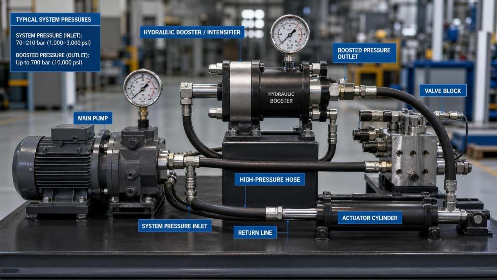
Hydraulic systems do not always need a larger pump when one actuator or one short portion of a cycle demands higher pressure. In many machines, the main requirement is stable flow for general motion, while only a clamping step, forming stroke, bolt tensioning action, or test function needs a pressure level above the pump’s normal rating. A hydraulic intensifier addresses that mismatch by converting available hydraulic energy into a smaller volume of higher-pressure fluid. The result is targeted pressure increase without redesigning the entire power unit.
This distinction matters because pump upgrades often create secondary changes. A larger or higher-pressure pump may require a different prime mover, modified relief settings, new hoses, upgraded manifolds, stronger seals, higher-rated valves, and more heat management. If the original system was sized correctly for flow and duty cycle, forcing the whole circuit upward can add cost and complexity in places that never needed extra pressure. Pressure boosting at the point of use can avoid that chain reaction.
How a hydraulic intensifier works in practice
A hydraulic intensifier uses a differential area principle. Lower-pressure oil acts on a larger piston area, and the generated force drives a smaller-area piston on the output side. Because pressure equals force divided by area, the smaller output area creates higher pressure. The tradeoff is straightforward: output flow is lower than input flow, and the boosted pressure is available only for limited volume or limited circuit sections unless the intensifier is designed for continuous duty.
That operating logic makes intensifiers useful where high pressure is intermittent. A press may need rapid approach at moderate pressure and only a short high-force finishing phase. A workholding circuit may need brief pressure multiplication to maintain clamp force on a small cylinder. A hydrostatic test station may require occasional pressure buildup after filling. In these situations, the machine still benefits from a pump selected around normal flow demand instead of peak pressure demand.
Some intensifiers are self-cycling units that repeatedly reciprocate to build output pressure until a preset level is reached. Others are integrated as compact in-line devices or manifold-mounted assemblies. Selection depends on whether the system needs a short pressure spike, a hold function with low leakage, or repeated high-pressure operation during every cycle.
When boosting pressure is usually the better engineering choice
The strongest case for an intensifier appears when only one branch of the hydraulic circuit needs higher pressure than the rest of the machine. If a bending fixture needs extra force but the transfer axes, lubrication circuits, and auxiliary cylinders operate well at standard pressure, raising the whole system can be wasteful. The same applies when an existing machine frame, tubing layout, and valve stack were originally built around a lower pressure class.
Another common situation involves retrofit work. A machine may already be installed in a plant, tied into existing electrical capacity, cooling arrangements, and maintenance routines. Replacing the pump might trigger a new motor selection, coupling review, shaft load verification, reservoir return line evaluation, and pressure rating audit across aged components. Adding an intensifier near the high-pressure consumer can keep the retrofit scope narrower, provided the local branch is isolated correctly and protected by suitable control and relief devices.
Pressure boosting also makes sense when the high-pressure demand is low volume by nature. Small-bore cylinders, hydraulic nuts, locking devices, test points, and brake release circuits often need pressure more than flow. In those cases, an intensifier can build pressure with acceptable cycle time because the fluid volume to be compressed is small. If the downstream actuator has a large swept volume and must move quickly under boosted pressure, the intensifier may become too slow or too thermally stressed.
There is also a commercial reason to prefer localized boosting: component availability. A full pump replacement may force redesign around a pump family with different mounting, shaft standards, case drain requirements, or control logic. A properly specified intensifier can sometimes fit into a manifold block, skid edge, or guarded subassembly with less disruption to machining, piping, and assembly drawings.
Cases where a pump upgrade is still the cleaner answer
An intensifier is not a universal substitute for a stronger hydraulic power unit. If the machine routinely needs both high pressure and substantial flow across multiple actuators, the energy bottleneck remains. Intensifiers multiply pressure by sacrificing output flow, so they cannot replace a pump when the core problem is undersized system capacity. A slow press stroke, weak travel motion under load, or repeated pressure collapse across several branches usually points back to pump sizing, leakage, or control issues rather than a need for pressure multiplication.
Continuous-duty applications deserve caution as well. Repeated cycling of an intensifier can generate heat, increase pulsation, and accelerate wear in seals and check valves. In a production environment with long duty periods, those effects may outweigh the initial savings. If the entire hydraulic architecture is being designed from zero, it is often cleaner to size the pump and valves around the real operating envelope instead of adding a booster to compensate for an early assumption.
Another warning sign is when upstream components are already close to their pressure limits. An intensifier may only raise pressure in the secondary side, but the act of integrating it still requires careful review of pilot lines, relief arrangements, adapters, gauges, fittings, and cylinder ratings. If downstream hardware is not clearly rated for the intensified pressure, the system becomes difficult to justify.
Pressure ratio is only the starting point
Selection discussions often begin with pressure ratio, such as 2:1 or 4:1, but actual suitability depends on the full operating window. The input pressure range matters because the output pressure is derived from it and reduced by internal losses. Seal friction, leakage, and dynamic response all influence whether the required pressure is reached consistently. A nominal ratio on a catalog page does not guarantee the same result at operating temperature, with the actual hydraulic oil viscosity, or under cycling conditions with trapped air still present.
Volume requirement is equally important. Engineers sometimes calculate target pressure correctly and then underestimate the amount of oil that must be delivered at that pressure. Compression of the oil, expansion of hoses, slight deformation of tubing, seal movement, and actuator dead volume all affect fill time. In a long hose run or a circuit with flexible lines, the intensifier may spend a noticeable part of the cycle building pressure into line elasticity before useful work begins.
Response behavior deserves attention too. Some applications tolerate a short delay before peak pressure arrives; others need a sharp and repeatable force rise. In clamping, stamping, or synchronized fixture actions, pressure lag can affect process timing. A booster that technically reaches target pressure but does so unpredictably may create production inconsistency even when static calculations look correct.
Materials, seals, and fluid compatibility
The intensified side of the assembly sees higher mechanical stress, so body material, piston finish, seal design, and check valve construction are not secondary details. Hardened steel components may be preferred in compact high-pressure units because repeated loading can be severe at contact points and sealing edges. Surface finish on the piston and bore influences seal life and leakage stability. Poor finish quality may not fail immediately, but it often appears later as pressure creep, erratic cycling, or contamination from accelerated wear particles.
Seal selection should match both pressure and fluid chemistry. Mineral oil systems, water-glycol fluids, and fire-resistant fluids do not treat elastomers the same way. Temperature range also matters because seal hardness changes response and leakage characteristics. If an intensifier is added to a machine operating outdoors, near a furnace, or in washdown areas, the seal package should be reviewed along with corrosion resistance for the housing, fasteners, and ports.
Contamination control becomes more sensitive as pressure rises. Fine particles that might pass unnoticed in a moderate-pressure circuit can damage small check valves or score precision bores in a booster assembly. If the application has a history of dirt ingress, worn pump debris, or inconsistent filtration during maintenance, an intensifier may expose those weaknesses quickly. Clean assembly, flushing of new lines, and filter placement are part of successful commissioning, not afterthoughts.
Installation details that decide whether the concept works
Line routing affects performance more than many layouts suggest. Mounting the intensifier close to the high-pressure consumer reduces compressible volume and improves response. Long small-diameter hoses between the intensifier and actuator can turn a fast pressure event into a soft one. Rigid tubing may be preferred where vibration and routing permit, especially in systems that repeat high-pressure cycles.
Pressure protection has to be arranged deliberately. The intensified branch usually needs its own relief strategy, and gauge range must match the expected output pressure. Standard gauges used on the main hydraulic circuit may be unsuitable on the boosted side. The same review applies to adapters, test points, and manifold plugs. A system can be correctly engineered in principle and still fail at a minor threaded connection chosen from the wrong pressure class.
Bleeding air from the high-pressure section is another practical issue. Trapped air compresses much more than hydraulic oil, reducing stiffness and making pressure buildup feel inconsistent. During startup, it is common to see an intensifier cycle more than expected simply because air remains in the branch or in the actuator cavity. Stable readings usually come only after careful venting and several controlled cycles.
Common misreadings during specification and procurement
One frequent mistake is treating required actuator force as proof that the whole hydraulic system must run at that pressure. Force should be traced back through cylinder area, motion profile, duty cycle, and the exact stage of operation. In many machines, high force is needed only after the actuator has already completed most of its travel at low resistance. That is a classic intensifier application.
Another mistake is assuming that a pressure multiplier removes the need to check downstream mechanical strength. Cylinder tie rods, gland retention, end caps, valve cavities, and manifold blocks must tolerate the intensified pressure. If those items were originally selected close to the base system pressure, a local booster can shift the weak point somewhere unexpected.
Documentation gaps also create risk. Quotations for boosters sometimes state maximum pressure and ratio clearly but leave cycle rate, fluid cleanliness requirement, seal material, and mounting orientation unclear. Those details matter in real installations. Transport and storage conditions can matter as well, especially when seals may sit for long periods before installation or when corrosion protection on exposed machined ports is inadequate.
Machining and manufacturing quality behind the component
Even though an intensifier is a hydraulic function device, its reliability depends heavily on machining quality. Piston concentricity, bore roundness, surface roughness, seat geometry for check valves, and thread integrity at ports all influence leakage and fatigue behavior. If the housing is a machined steel block or a forged body with subsequent finishing, dimensional control after heat treatment can affect alignment and seal compression. Small deviations that seem acceptable in low-pressure service may become troublesome once pressure is multiplied.
For integrated manifold designs, the machining path of cross-drilled passages and cavity transitions deserves review. Sharp internal edges, residual burrs, or poor cleaning after machining can damage seals or obstruct valve movement during first operation. In systems connected to fabricated piping or cast valve blocks, matching flatness at mounting faces and cleanliness of connecting passages should be treated as functional requirements, not cosmetic ones.
Evaluating suitability before release
A useful engineering review usually starts with four linked questions: where the higher pressure is actually needed, how much fluid volume must be intensified, how often the event repeats, and what the downstream components are rated to withstand. From there, the design can be checked for thermal load, response time, pulsation tolerance, maintenance access, and spare part clarity. If any of those areas remain vague, the apparent simplicity of adding a booster can disappear during commissioning.
When those conditions are understood, hydraulic intensifiers can be a precise way to solve a pressure problem without rebuilding an otherwise balanced system. They are most convincing in circuits with localized, low-volume, intermittent high-pressure demand and least convincing where the machine fundamentally lacks pump capacity.