
How to Size Hydraulic Accumulators for Stable Hydraulic Power Unit Output
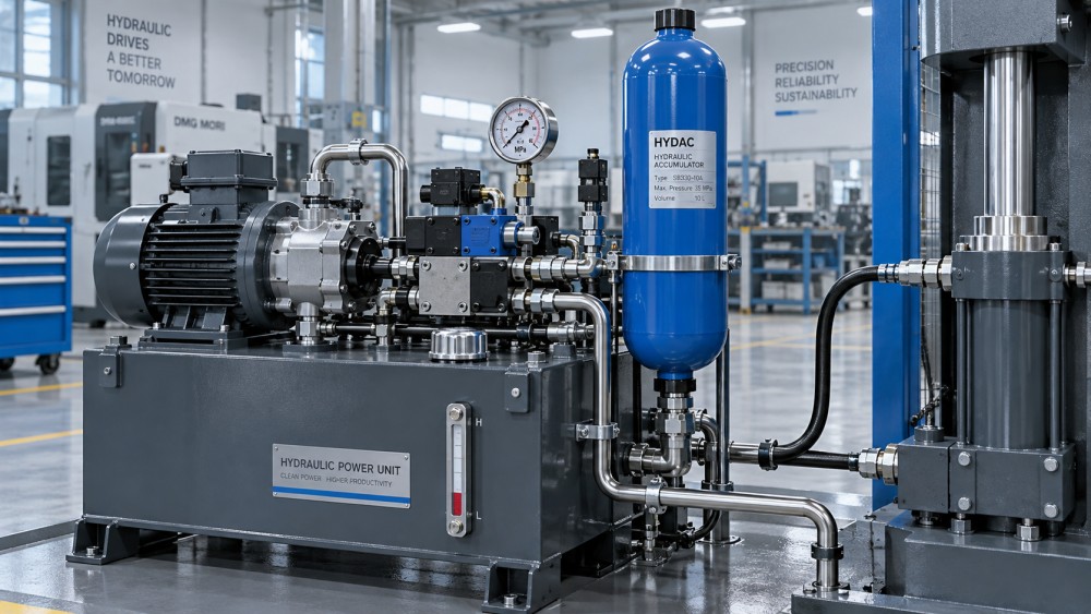
A hydraulic power unit can look perfectly adequate on a schematic yet still deliver unstable pressure at the machine. A pump may be correctly selected, the relief valve may be set properly, and the reservoir may be generous—while rapid cylinder movement, intermittent clamping demand, or a pump start-stop sequence creates pressure dips that affect the actual process. This is where hydraulic accumulators for hydraulic power units become more than an accessory. Correctly sized, they store usable fluid energy, absorb transients, and give the system a steadier operating rhythm.
For technical evaluators, accumulator sizing is not a matter of selecting the largest available shell volume. The useful oil volume delivered by an accumulator changes with pressure, gas precharge, temperature, duty cycle, and the allowable pressure band. An oversized unit can add cost, installation complexity, and safety requirements without solving the real issue. An undersized unit may appear functional during a short trial but lose its value once the machine enters full production.
The practical objective is simple: define the fluid volume the accumulator must supply or absorb, then confirm that a real accumulator can deliver that volume between the system’s maximum and minimum acceptable pressures.
Start with the hydraulic event, not the accumulator catalog
Before calculating shell volume, identify what the accumulator is expected to do inside the hydraulic power unit. The application determines the sizing method and the pressure range that matters.
- Emergency or reserve power: supplying fluid long enough to bring a cylinder, valve, brake, or clamp to a safe position after pump power is lost.
- Peak-flow assistance: supplementing pump flow during a short, high-demand machine movement.
- Leakage compensation: maintaining pressure in a clamping or holding circuit while the main pump is idle.
- Pulsation and pressure stabilization: reducing flow ripple from piston pumps or mitigating fast demand changes near sensitive valves.
- Shock absorption: accepting sudden fluid displacement caused by load changes, thermal expansion, or fast valve closure.
- Energy recovery: storing energy during deceleration or lowering operations for later reuse where the circuit design permits it.
These duties should not be treated as interchangeable. A small bladder accumulator selected to smooth pump pulsation is rarely sufficient for a long emergency cylinder stroke. Conversely, an accumulator sized for reserve motion may need a different mounting location, isolation arrangement, and safety review than a compact pulsation damper.
In a hydraulic press, for example, the key question may be how much oil is needed to maintain clamping force during a brief pump pause. In a mobile machine, the question may be how much peak flow is required to accelerate an actuator without installing a larger continuously running pump. For a municipal or industrial fluid-control skid, the concern may be pressure stability during frequent valve operation. The duty cycle gives the calculation its meaning.
Define the four pressures that govern usable capacity
Accumulator calculations are often weakened by using nominal system pressure as the only input. In reality, evaluators need to establish a working pressure window and relate it to the gas precharge.
A common starting point for energy storage applications is to set nitrogen precharge below the minimum working pressure, often around 90% of P1. The correct margin depends on the manufacturer’s guidance, temperature conditions, response time, and accumulator type. If the precharge is too high, the bladder or piston may not admit enough oil at the low end of the operating range. If it is too low, the gas side can be excessively compressed at full charge, reducing service life and potentially creating poor response characteristics.
All pressure calculations should use absolute pressure, not gauge pressure. Add atmospheric pressure to gauge readings before applying gas-law equations. This detail is easy to miss and can create meaningful error in lower-pressure systems.
The sizing relationship: required oil volume comes first
For a peak-flow or reserve-energy duty, calculate the hydraulic fluid volume required by the event:
Required fluid volume = flow deficit × event duration
For example, if a machine requires 50 L/min for a rapid movement, while the pump continuously supplies 30 L/min, the accumulator must contribute a 20 L/min deficit. If that deficit lasts 6 seconds, the required delivery is approximately 2 L of oil. That 2 L is not the accumulator’s nominal volume. It is the usable oil volume the accumulator must release while pressure falls from P2 to P1.
For cylinder applications, derive the required volume from the effective piston area and stroke, then include line volume, expected leakage, and any simultaneous consumers. A rod-side retract volume is different from a cap-side extend volume. In circuits with differential or regenerative motion, the actual flow balance must be checked rather than assumed from bore diameter alone.
For pressure maintenance, the demand may be driven less by cylinder motion and more by internal valve leakage, external leakage, temperature-related volume change, and the allowable interval between pump restarts. In that case, the design target is often a stable pressure band and a defined pump cycling frequency.
Using the gas law to determine nominal accumulator size
Most accumulator sizing for hydraulic power units uses the polytropic gas relationship:
P × Vn = constant
Here, P is absolute gas pressure, V is gas volume, and n reflects the heat transfer condition. A slowly changing cycle may behave closer to isothermal compression, while a rapid discharge or charge is closer to adiabatic behavior. In practice, manufacturers commonly provide sizing software, charts, or correction factors because real duty cycles sit between these ideal conditions.
For preliminary evaluation, the usable oil volume delivered between P2 and P1 can be estimated from the change in gas volume. The nominal gas volume V0 must be large enough that this change equals or exceeds the required hydraulic oil volume. A technical review should account for temperature, gas permeation over time, precharge tolerance, and the fact that the system may not always recharge to its intended maximum pressure.
The important insight is that usable capacity is controlled by the pressure ratio. A wide allowable pressure drop allows more oil to be released from a given shell size. A narrow pressure band requires a larger accumulator, even if the system pressure itself is high. This is why a unit that seems ample on paper may provide little useful volume in a circuit that can only tolerate a small pressure decline.
Temperature and cycle speed can change the answer
A nitrogen-charged accumulator is a thermodynamic device. Gas pressure changes not only because oil enters or leaves, but also because gas temperature changes. On a fast machine cycle, compression can heat the gas and temporarily elevate pressure. During a slower hold period, the gas cools and pressure falls. If an accumulator is sized only from room-temperature nominal values, the resulting pressure behavior may be disappointing in a high-cycle production environment.
Temperature deserves particular attention when the power unit operates outdoors, near furnaces, in cold-start conditions, or with long idle periods. A lower ambient temperature reduces precharge pressure. A system that works at commissioning temperature may deliver less energy at low temperature, or may have an altered minimum-pressure margin. Confirm the expected minimum and maximum gas temperatures, then follow the accumulator supplier’s precharge adjustment guidance.
Cycle rate also influences accumulator construction. Bladder accumulators are widely used for rapid response and compact installation. Piston accumulators can be suitable for larger volumes, higher flow duties, or applications requiring a separation arrangement compatible with the circuit. Diaphragm accumulators may suit smaller-volume and pulsation-control tasks. Selection should consider more than volume: flow rate, fluid compatibility, orientation, maintenance access, and the expected number of cycles all matter.
Precharge is a commissioning value, not a one-time label
Even a well-sized accumulator can fail to stabilize a hydraulic power unit if its nitrogen precharge is wrong. A charge that has drifted downward can cause excessive fluid entry, reduced effective gas spring behavior, and possible damage in some accumulator designs. Excessive precharge can leave too little stored oil available when the system reaches its minimum operating pressure.
Precharge should be checked with the accumulator isolated and fully depressurized on the hydraulic side, using suitable charging equipment and procedures. Never use compressed air or oxygen; nitrogen is used because it is inert and compatible with standard accumulator practice. The check should be part of planned maintenance, particularly where frequent cycling, temperature variation, or long operating hours are expected.
For evaluators comparing hydraulic accumulators for hydraulic power units, ask whether the supplier provides clear information on precharge limits, service kits, gas valve protection, maintenance intervals, and documentation for the pressure vessel. These details influence lifecycle suitability just as much as initial capacity.
System details that can quietly invalidate a correct calculation
Accumulator sizing should be reviewed alongside the full hydraulic circuit. Several practical issues repeatedly create a gap between calculated and observed performance.
- Pressure losses in pipes and valves: If the accumulator is remote from the point of demand, hose friction and restrictive check valves can consume the pressure margin assumed in the calculation.
- Incorrect check-valve arrangement: The accumulator must be able to charge and discharge as intended without back-feeding an unwanted part of the system.
- Ignoring pump recharge time: A unit may supply a short peak successfully but fail during repeated cycles because the pump cannot restore charge before the next demand.
- Unrealistic duty-cycle assumptions: A single motion test does not represent production. Consider the shortest interval between peak events, cold oil viscosity, and simultaneous functions.
- Mounting and vibration: Heavy industrial equipment requires proper brackets and piping support. An accumulator shell should not be supported by hydraulic lines alone.
- No safe isolation or discharge provision: Stored hydraulic energy remains hazardous after the pump stops. Isolation, pressure relief, and controlled depressurization must be considered in the design.
Contamination control also deserves attention. The accumulator does not replace filtration, reservoir design, or clean assembly practice. Contaminated fluid can impair valves and pumps, leading engineers to blame pressure instability on accumulator capacity when the actual cause is sticking control hardware or degraded fluid condition.
A practical selection workflow for technical evaluation
A disciplined review can be completed without overcomplicating the procurement process. Begin by recording the required motion, flow deficit, or pressure-maintenance demand in real operating units. Establish the minimum acceptable pressure at the actuator or valve—not merely at the power-unit outlet. Then determine the normal maximum charge pressure, allowing for pump control settings and pressure losses.
Next, select a preliminary precharge strategy and calculate usable fluid volume with absolute pressures and an appropriate gas-process assumption. Apply a margin for temperature variation, recharge behavior, normal precharge loss, and uncertainty in the machine’s actual demand profile. Review candidate accumulator types against flow rate, cycle frequency, fluid, pressure rating, installation space, and applicable local pressure-equipment requirements.
Finally, validate the selection on the circuit rather than in isolation. Trend pressure during the fastest and most demanding sequence. Watch the pressure at the point of use, pump start frequency, recharge time, oil temperature, and any unexpected valve response. A stable trace across repeated cycles is more valuable than a theoretical result based on ideal conditions.
What a well-matched accumulator changes
The best outcome is not simply a larger stored-energy reserve. A properly sized accumulator can let a hydraulic power unit operate with calmer pressure behavior, lower short-duration pump demand, fewer unnecessary starts, and more predictable actuator performance. For machinery builders, that can support a smaller or more efficiently controlled pump package. For maintenance teams, it can reduce the mystery surrounding intermittent pressure drops and erratic motion.
Still, an accumulator should be treated as part of a coordinated fluid-power design. Pump capability, relief settings, valve response, piping losses, oil cleanliness, temperature management, and safety controls all shape the result. By sizing from the real duty cycle and the usable pressure window—not from nominal shell volume alone—technical evaluators can select an accumulator that contributes measurable stability to the hydraulic power unit and remains practical to maintain over its operating life.
Related News
- Using Industrial Air Blow Guns to Clear Chips Without Spreading DebrisOct 15, 2026Fluid Power Control Strategist
- Ductile Iron Pipe Valves: Which AWWA Standards Apply to Water Main Projects?Oct 15, 2026Dr. Elias Vance
- Why Vacuum Suction Cups Lose Grip on MDF in Woodworking MachinesOct 15, 2026CNC Kinematics Architect
- Choosing a Variable Displacement Piston Pump Manufacturer: What to VerifyOct 15, 2026Fluid Power Control Strategist
- Parallel vs. Angular Pneumatic Grippers for Confined Assembly StationsOct 15, 2026Fluid Power Control Strategist
- Die Castings vs. Investment Castings: Which Costs Less at Your Production Volume?Oct 14, 2026Foundry Phase-Change Fellow