
How to Size Axial Piston Pumps for High-Pressure Hydraulic Machinery
Start with the Work Cycle, Not the Catalog Flow Rating
High-pressure hydraulic machinery is often oversized at the pump selection stage because the design team begins with a maximum actuator flow and a maximum pressure, then assumes both occur together for most of the operating day. In many machines, they do not. A press may need high flow during approach and high pressure only during forming. A mobile machine may see short peak loads separated by low-demand travel. A test rig may hold pressure for long periods while consuming very little flow.
That distinction determines whether an axial piston pump should be sized for continuous delivery, intermittent peaks, or a variable-demand profile. Selecting a larger displacement pump simply to cover a brief pressure event can increase installed motor power, heat rejection requirements, and control instability. Selecting too small a pump can extend cycle time, starve critical functions, and force the pump to operate near its limits too often.
For a project manager, the first useful sizing document is therefore a duty-cycle table rather than a supplier quotation request. It should show each machine function, required flow, required pressure, duration, frequency, whether motions overlap, and whether the load is resistive or overrunning. This converts a vague requirement such as “high-pressure hydraulic system” into a load profile that can be checked.
A variable-displacement axial piston pump is particularly useful when flow demand changes widely while pressure must remain controlled. Its nominal displacement still has to meet the required maximum usable flow at the available input speed, but its control system can reduce displacement when the machine is unloaded or when only a small holding flow is needed. That capability is valuable only when the machine’s operating profile and valve architecture allow it to be used properly.
Calculate Flow from Motion Requirements
Pump flow is determined by what the actuators must do within the required time. For a cylinder, calculate the oil volume needed for the intended stroke and divide it by the required stroke time. For a hydraulic motor, calculate required speed from its displacement and include expected volumetric losses. The result should be based on the actual machine sequence, not on a nominal flow value copied from a preceding design.
For preliminary pump sizing, theoretical pump flow can be expressed as:
Q = D x n x eta_v
Where Q is delivered flow, D is pump displacement per revolution, n is input speed, and eta_v is volumetric efficiency. Units must remain consistent. A pump’s published displacement describes theoretical volume per revolution; it does not guarantee that the same volume reaches the system at every pressure, temperature, speed, and fluid condition.
Volumetric efficiency falls as internal leakage rises. Leakage is influenced by pressure, fluid viscosity, component clearance, temperature, wear, and pump condition. A sizing calculation that assumes theoretical delivery without allowing for volumetric efficiency may work on paper but miss the machine’s required cycle time after the hydraulic oil reaches normal operating temperature.
Do not automatically add every actuator’s maximum flow together. The correct question is which functions can operate at the same time under the machine control logic. A boom lift and a swing motor may overlap during one operating mode; clamp movement and a press forming stroke may be interlocked. The hydraulic schematic, PLC sequence, and operator behavior all affect the credible simultaneous demand.
Where demand peaks are brief and repeatable, an accumulator or a separate high-flow/low-pressure circuit may be more appropriate than enlarging the main high-pressure pump. That decision requires careful analysis of safety, stored energy, recharge time, pressure decay, and maintenance requirements. It should not be used merely to conceal an undersized pump.
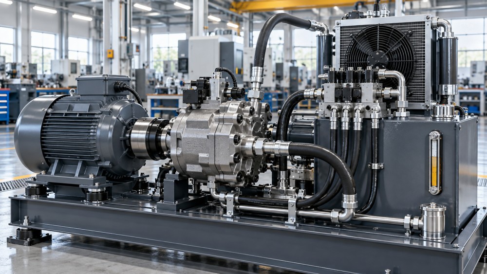
Pressure Rating Is Only One Part of the High-Pressure Decision
Matching a pump’s maximum pressure rating to the relief-valve setting is insufficient. The pump must tolerate the expected operating pressure, pressure ripple, transient spikes, and the time spent under load. The relevant rating may differ between continuous operation, intermittent operation, and short-duration peak operation. Project specifications should distinguish these conditions rather than treating a single maximum-pressure number as a complete description.
Pressure losses between the pump outlet and the working actuator also matter. Hoses, pipes, fittings, filters, cooler passages, manifolds, valves, and quick couplings all consume pressure. The pump outlet pressure has to cover the actuator load plus the losses in the active flow path. At high flow, even a system designed around a reasonable cylinder force can demand substantially more pump pressure because of restrictions introduced by undersized lines or valve sections.
This is one reason pump sizing should be reviewed together with piping and valve selection. A pump cannot correct a restrictive circuit efficiently. Raising the pressure setting to recover lost actuator performance increases shaft torque, oil heating, stress on seals and hoses, and the consequences of a relief event. In a high-pressure machine, pressure-drop calculations should be performed for the actual fluid viscosity range and expected flow, including return-side restrictions that can affect actuator behavior.
Transient conditions deserve separate attention. Rapid directional-valve shifts, sudden deceleration of inertia, blocked flow paths, and load reversals can create spikes beyond the steady-state calculation. Cross-port relief valves, decompression functions, accumulator damping, controlled ramp rates, and correctly located pressure relief devices may all be part of the solution. The pump selection must be compatible with the pressure-control strategy rather than relying on the pump’s headline maximum rating as protection.
Check Drive Torque and Installed Power at the Real Operating Point
A pump can deliver the required flow and still be a poor system choice if the electric motor, engine, gearbox, coupling, or power take-off cannot provide adequate torque at the most demanding point. Hydraulic power rises with both flow and pressure. A commonly used relationship is:
Hydraulic power = pressure x flow
The input power must then be higher than hydraulic output because mechanical and volumetric losses consume energy. For design work, use pump efficiency values appropriate to the expected pressure, speed, displacement setting, and fluid temperature. Do not base motor sizing solely on a best-case efficiency figure from a performance chart.
Variable-displacement axial piston pumps require particular care because maximum torque may occur at high pressure and high displacement. A machine may not normally command that condition, but a control fault, cold start, relief setting, or commissioning sequence can expose the drive to it. The design should define whether the prime mover can safely handle full displacement at maximum system pressure, or whether torque-limiting controls, displacement limits, or start-up controls are required.
Electric-motor applications need a coordinated review of starting method, overload capacity, variable-frequency-drive limits, and the pump’s minimum and maximum allowable speed. Engine-driven systems need to account for available torque across engine speed, not just rated horsepower. Coupling and gearbox ratings should be checked for cyclic torque, misalignment limits, and torsional effects, especially where large pump displacements or rapid pressure changes are involved.
Size the Suction Side Before It Becomes a Reliability Problem
Many high-pressure pump failures begin at the inlet, not at the outlet. Axial piston pumps depend on adequate inlet conditions to fill the pumping chambers. If the suction line is too small, too long, poorly routed, restricted by an unsuitable strainer, or exposed to excessive elevation lift, inlet pressure can fall below what the pump needs. The resulting cavitation or aeration can damage rotating groups, increase noise, destabilize pressure control, and shorten service life.
The suction design must be assessed at cold-start viscosity as well as normal operating temperature. Cold oil raises line losses and can make a system that runs acceptably when warm difficult to start or noisy during initial operation. Reservoir placement, fluid level, return-line arrangement, breather condition, suction hose construction, and fittings all influence inlet performance.
For systems operating in dusty, humid, mobile, or remote environments, contamination control has to be included in the sizing decision. High-pressure axial piston units have precision internal surfaces and are sensitive to particulate contamination. Filter placement and micron rating should follow the pump and valve requirements, but the filter must also have enough flow capacity that restriction remains acceptable throughout its service interval. A small filter selected only by nominal flow can generate avoidable pressure drop as it loads.
Oil temperature is linked directly to pump capacity and life. If the pump is oversized and repeatedly unloads across a relief valve, energy becomes heat. If a pump operates at low efficiency under a demanding pressure profile, heat again becomes a system constraint. Cooler capacity should be evaluated from expected losses over the duty cycle, not from a short peak-power calculation. A system that reaches acceptable pressure during commissioning may still overheat during a long production shift.
Choose the Control Concept Along with the Pump
“Axial piston pump” describes a pump architecture, not a complete operating solution. Fixed-displacement units, pressure-compensated pumps, load-sensing pumps, electro-proportional displacement controls, and torque-limited controls behave differently under changing loads. The control choice determines how much power the machine draws when it is idle, how quickly pressure responds, how the pump shares flow with other functions, and whether instability is likely at low demand.
A pressure-compensated pump can suit equipment that needs pressure available on demand and has limited concurrent flow requirements. However, it may generate unnecessary heat if the system frequently holds pressure while excess flow is forced through a relief path. A load-sensing arrangement can reduce wasted flow in machines with changing actuator demand, provided the sensing lines, compensator settings, valve margins, and priority functions are designed as a stable system.
Electro-hydraulic controls may improve repeatability and energy management in presses, machine tools, and automated equipment, but they introduce requirements for sensors, calibration, software behavior, fault response, and commissioning capability. A project should not specify an advanced pump controller without deciding who will set it up, diagnose it, and maintain its configuration after handover.
Build Margin Around Uncertainty, Not Around Every Number
Every hydraulic design needs margin, but indiscriminate margin produces an oversized and inefficient package. A useful approach is to identify where uncertainty actually exists: expected material load, future tooling changes, fluid temperature range, altitude, line routing, simultaneous functions, allowable cycle-time variation, and deterioration between maintenance intervals. Margin can then be assigned to the relevant variable.
For example, uncertainty in future production rate may justify additional flow capacity. Uncertainty in shock loading may justify a higher pressure capability and better transient protection. Uncertainty in cold-start behavior may require a more conservative inlet design or a controlled warm-up sequence. These are different engineering responses. Adding pump displacement to solve all of them usually addresses none of them well.
The final selection should be checked against a concise set of operating cases: cold start, normal production, maximum load, simultaneous-function demand, pressure hold, emergency stop, and degraded conditions such as a partially loaded filter. For each case, verify flow, pressure, shaft torque, input power, inlet condition, heat generation, and control response. This review gives the project team a defensible basis for selecting axial piston pumps that support the required machine output without transferring avoidable risk into the drive, piping, cooling, or maintenance system.
Related News
- How to Assess a Rigid Coupling Supplier for Bore Accuracy and Traceable QualityOct 08, 2026Tribology & Kinematics Expert
- Titanium Alloys Compared: Balancing Strength, Corrosion Resistance, and MachinabilityOct 08, 2026CNC Kinematics Architect
- Where Ductile Iron Dismantling Joints Reduce Alignment Risk in Water PipelinesOct 08, 2026Pipeline Metallurgy Scientist
- Selecting a Precision Bearing Sleeve: Fits, Runout, and Material ChoicesOct 08, 2026Tribology & Kinematics Expert
- Face Milling Cutters: How Insert Geometry Affects Finish on Steel and AluminumOct 08, 2026CNC Kinematics Architect
- Single-Acting Cylinders for Clamping: Stroke, Force, and Return Spring ConsiderationsOct 07, 2026Fluid Power Control Strategist