
How to Match Hydraulic Motor Torque and Speed to Drilling Rig Operating Conditions
How to Match Hydraulic Motor Torque and Speed to Drilling Rig Operating Conditions
Selecting hydraulic motors for drilling rigs is not a matter of finding the highest torque figure in a catalog. A motor that looks adequate on paper can still stall during difficult ground conditions, run too slowly during shallow drilling, overheat on long duty cycles, or place unnecessary stress on the gearbox, rotary head, hoses, and pump.
For project managers, the practical question is simpler: can the rotary drive maintain usable drilling speed while producing enough torque for the hardest expected section of the job? The answer depends on more than the drill diameter. Ground formation, drilling method, depth, tool string weight, available hydraulic flow, pressure limits, and operator working habits all affect the required motor selection.
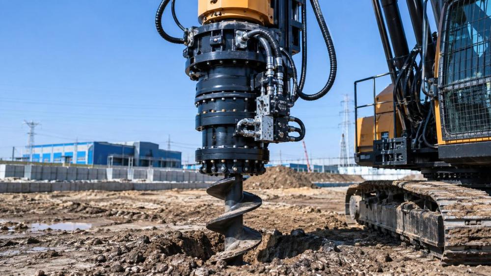
This is especially relevant when evaluating hydraulic motors for drilling rigs used in foundation work, water well drilling, geotechnical investigation, mining, utility installation, or auger-based construction. The right match is a system decision. The motor, pump, control valve, reduction gearbox, couplings, bearings, and cooling arrangement must work together under actual operating conditions rather than ideal test conditions.
Start With the Drilling Task, Not the Motor Catalog
A rig may perform several very different jobs over its working life. Drilling a relatively shallow bore in loose soil is not comparable to advancing a large-diameter auger through compacted clay, fractured rock, mixed fill, or water-bearing formations. If a project team defines the motor only by nominal rig size, it can miss the loads that actually create downtime.
The first step is to describe the operating envelope. This should include the drilling tool diameter, expected drilling depth, formation profile where available, intended rotation speed range, drilling method, anticipated breakout torque, and whether the motor will run continuously or mainly in short cycles. Reverse rotation, casing installation, tool extraction, and stuck-tool recovery should also be considered. These events may be occasional, but they often determine the peak torque requirement.
A common mistake is sizing a motor around average drilling resistance. Average conditions may govern fuel use and productivity, but peak resistance governs whether the rig completes the difficult part of the hole without repeated stalling. At the same time, specifying only for the highest imaginable torque can produce a slow, inefficient drive that spends most of its life operating outside its most useful speed range.
Understand the Torque, Pressure, Flow, and Speed Relationship
Hydraulic motor behavior is built around two basic relationships. Motor torque is primarily linked to pressure differential and displacement. Motor speed is primarily linked to hydraulic flow and displacement. In simplified engineering terms, theoretical torque rises with pressure and motor displacement, while theoretical speed falls as displacement increases at a fixed flow rate.
That is why a larger-displacement motor is often selected where low-speed, high-torque rotation is needed. However, it will require more oil flow to achieve the same rpm as a smaller motor. If the existing pump cannot supply that flow, drilling speed may be disappointing even though the torque rating appears generous.
Actual field performance is lower than theoretical performance because of mechanical and volumetric losses. Internal leakage increases as components wear, oil temperature rises, or pressure becomes severe. For planning purposes, project teams should use manufacturer performance curves rather than relying only on a displacement calculation. Those curves show the practical relationship among pressure, flow, output torque, speed, efficiency, and permissible continuous operation.
The motor must also be evaluated at the pressure available at the motor ports, not merely the pressure setting on the power unit. Pressure losses through long hoses, restrictive fittings, directional valves, rotary manifolds, filters, and cooling circuits can be material in a high-flow rig. A system may have adequate relief pressure at the pump and still deliver less usable torque at the rotary head than expected.
Separate Rotary Head Torque From Motor Torque
Many drilling rigs use a reduction gearbox between the hydraulic motor and the drill string. This changes the selection problem. The motor does not necessarily need to produce the full torque demanded at the drill head because gearbox reduction multiplies output torque. In exchange, rotary head speed falls relative to motor speed.
For example, a rig requiring slow, powerful auger rotation may use a motor that operates efficiently at a higher rpm, paired with a suitable planetary gearbox. The gearbox ratio, mechanical efficiency, allowable input speed, output bearing capacity, and shock-load capability all matter. It is not safe to calculate output torque by multiplying motor torque by gear ratio alone; gearbox losses and allowable mechanical limits must be included.
This is where mechanical power transmission details become important. A motor may survive the hydraulic load while the gearbox output shaft, spline, coupling, or drill-head bearing does not. High breakout torque is particularly demanding because the drill string can behave like a torsional spring. When the bit suddenly releases, stored energy can create a transient load that is very different from steady drilling torque.
A well-matched drive therefore needs a defined torque limit. Relief valves, cross-port relief protection, pressure-reducing arrangements, and control logic may be used depending on the rig design. The goal is not simply to protect the motor. It is to prevent a stalled tool or abrupt reversal from damaging the entire rotating assembly.
Choose a Motor Type That Fits the Duty Cycle
Different hydraulic motor designs have different strengths. Gear motors are often valued for simplicity and cost control, but may not be the preferred option where precise low-speed operation, very high torque, or frequent load reversals are central to the application. Gerotor and orbital motors can suit many low-speed, moderate-to-high-torque duties, provided their pressure, side-load, and thermal limits fit the rig.
Piston motors are widely considered where drilling equipment needs higher pressure capability, demanding duty cycles, broader speed control, or variable displacement. A variable-displacement piston motor can be useful when one rig must perform both fast, lower-torque drilling and slower, high-torque work. That flexibility has a cost and adds control complexity, so it should be justified by the operating profile rather than selected automatically.
Continuous and intermittent ratings deserve close attention. A motor may tolerate a high-pressure condition for a limited period but not for a long drilling interval. Projects with repeated deep holes, long casing runs, or high ambient temperatures should be assessed around continuous operating conditions. A short peak rating is not a substitute for thermal capacity.
Do Not Ignore Low-Speed Stability
Drilling does not always benefit from maximum rpm. In difficult formations, operators may need to rotate slowly while maintaining steady torque and feed pressure. If the motor has poor low-speed characteristics, the rotary head can move in pulses rather than smoothly. This can make drilling less controllable, increase vibration, disturb borehole quality, and place extra stress on teeth, couplings, and threaded drill connections.
Low-speed stability depends on motor design, control valve behavior, oil cleanliness, fluid viscosity, and the interaction between motor torque and the load. A proportional valve or well-tuned flow-control arrangement may improve controllability, but it cannot fully correct an unsuitable motor selection. When a rig must perform controlled slow rotation, request data for minimum stable speed under load rather than assuming a published minimum rpm applies to every field condition.
This is also a reason to look beyond the motor itself. Poorly sized hoses, restrictive return lines, contaminated filters, or a weak charge circuit can make a capable motor appear unreliable. In hydraulic and pneumatic equipment, component compatibility often determines the result more than the nameplate rating of one individual part.
Check Heat, Oil Cleanliness, and Drain Requirements Early
Heat is often treated as a maintenance issue, but it begins as a sizing issue. When a motor is routinely forced to operate near relief pressure, hydraulic energy is converted into heat rather than useful rotation. The usual symptoms are slower response after warm-up, reduced efficiency, seal deterioration, and shortened life for both the motor and the hydraulic fluid.
Project specifications should confirm the power unit’s cooling capacity, tank design, expected ambient temperature, fluid grade, and contamination-control plan. A drilling rig working outdoors faces dust, water, vibration, and hose damage risks that are very different from a stationary industrial machine. Filter selection, reservoir breathers, flushing procedures, and replacement parts availability should be part of the equipment review.
Some motor designs require a case-drain line and have strict limits on case pressure. This detail can be missed during retrofits, especially when an older rig is upgraded with a different motor family. Incorrect case-drain routing can damage shaft seals or internal components even if the pressure and flow calculations appear correct.
Build a Selection Sheet Around Real Constraints
Before approving a hydraulic motor, the project team should collect the information that suppliers and design engineers actually need: pump flow range, normal and relief pressure settings, target rotary head rpm, required continuous and peak drill-head torque, gearbox ratio, expected drill tools, hose dimensions, return-line arrangement, ambient conditions, and duty cycle. Drawings of the mounting interface and shaft or spline connection are equally important.
For a new rig, this information supports proper motor and transmission matching. For a replacement or retrofit, it prevents a frequent problem: installing a motor with the correct mounting flange but the wrong displacement, pressure range, drain configuration, or shaft load capacity. Physical interchangeability is not proof of hydraulic suitability.
Procurement teams should also ask whether the supplier can provide performance curves, dimensional drawings, mounting details, operating limits, fluid recommendations, spare-parts information, and documentation for critical materials or inspection where required by the project. For heavy-duty industrial equipment, technical communication before purchase is often a more useful indicator than a broad catalog description.
A Practical Decision for Long-Term Rig Reliability
The most suitable hydraulic motor is rarely the one with the largest displacement or the highest headline torque. It is the motor that delivers the required rotary-head torque through the intended gearbox, reaches useful drilling speed with the available flow, remains within continuous pressure and temperature limits, and can be controlled reliably at low speed when the ground becomes difficult.
For project managers comparing hydraulic motors for drilling rigs, the best starting point is a documented operating envelope rather than a part number. Once torque, speed, pressure, flow, duty cycle, and drivetrain limits are visible in one review, selection becomes much clearer. It also becomes easier to identify whether the real constraint is the motor, the pump, the gearbox, the cooling circuit, or the drilling method itself.
Platforms such as Global Industrial Machining & Piping Equipment Network help teams organize these linked considerations across fluid power, forged shafts, gearboxes, bearings, valves, and other heavy-duty components. That broader view matters because a drilling rig does not fail as a catalog page. It fails, or performs well, as a connected mechanical and hydraulic system.
Related News
- Using Industrial Air Blow Guns to Clear Chips Without Spreading DebrisOct 15, 2026Fluid Power Control Strategist
- Ductile Iron Pipe Valves: Which AWWA Standards Apply to Water Main Projects?Oct 15, 2026Dr. Elias Vance
- Why Vacuum Suction Cups Lose Grip on MDF in Woodworking MachinesOct 15, 2026CNC Kinematics Architect
- Choosing a Variable Displacement Piston Pump Manufacturer: What to VerifyOct 15, 2026Fluid Power Control Strategist
- Parallel vs. Angular Pneumatic Grippers for Confined Assembly StationsOct 15, 2026Fluid Power Control Strategist
- Die Castings vs. Investment Castings: Which Costs Less at Your Production Volume?Oct 14, 2026Foundry Phase-Change Fellow