
How a Hydraulic Intensifier Multiplies Pressure in Compact Industrial Systems
A compact hydraulic fixture may have enough flow to position a workpiece but not enough pressure to clamp it securely. A mobile service unit may fit inside a tight enclosure yet fall short of the force needed for a bolt-tensioning tool or a small press cylinder. In these situations, replacing the entire pump and motor package can increase cost, heat load, wiring requirements, and installation space.
A hydraulic intensifier addresses that mismatch by using a difference in piston areas to raise pressure in a smaller outlet circuit. It does not create energy from nothing: the higher outlet pressure is accompanied by lower available outlet flow and a smaller effective output volume. The practical value is that a system can generate high pressure only where it is needed, while the main pump continues operating at a lower, more manageable pressure.
The pressure multiplication principle
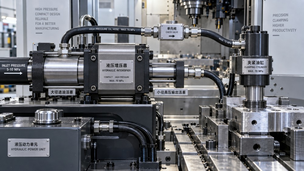
A hydraulic intensifier normally contains two mechanically connected pistons. The larger piston receives pressure from the supply side. Because pressure acts over a relatively large area, it produces a pushing force. That force is transferred through the piston rod to a smaller high-pressure piston. Since the same force now acts over a smaller area, pressure rises at the outlet.
The basic relationship can be expressed as:
Outlet pressure = inlet pressure × (large piston area ÷ small piston area)
For example, an intensifier with a 4:1 area ratio supplied at 100 bar can theoretically produce 400 bar at its high-pressure outlet. Actual output will be lower than the ideal figure because seals, springs, internal friction, pressure losses, and valve behavior consume part of the available force. The manufacturer’s rated pressure and stated intensification ratio should therefore be used for design work rather than relying only on a calculated ratio.
Area ratio, not piston diameter ratio, determines multiplication. Since piston area changes with the square of diameter, a piston that is twice the diameter of another has approximately four times the area. This is a frequent source of misunderstanding during early concept calculations.
Why high pressure comes with lower flow
The intensifier changes the pressure-and-flow balance; it does not eliminate it. The large supply piston must travel a greater volume to move the smaller high-pressure piston through its stroke. A 4:1 ratio means that, before accounting for leakage and losses, roughly four units of low-pressure fluid volume are needed to deliver one unit of high-pressure fluid volume.
This has a direct effect on machine behavior. A small clamping cylinder supplied through an intensifier may develop the required final force, but it will not extend at the same speed as it would with a large high-flow high-pressure pump. That is often acceptable because many machines need rapid approach at low force followed by a short high-force holding or forming stage.
Intensifiers are therefore best suited to applications with one or more of these characteristics:
- High pressure is needed only at the end of a stroke or during a brief operating phase.
- The high-pressure actuator has a relatively small fluid volume.
- A compact power unit must serve several functions at different pressure levels.
- The machine has limited space for a larger pump, motor, reservoir, or high-pressure piping network.
- Intermittent pressure boosting is more economical than continuously operating the whole circuit at high pressure.
A press that must continuously move a large cylinder under high pressure is usually not an ideal intensifier application. The required volume, cycle frequency, and heat generation can make a dedicated high-pressure pump more appropriate.
A typical compact-system sequence
Consider a machining fixture that must close quickly around a component and then apply a high clamp load before a cutting cycle begins. Running the whole fixture circuit at the final clamping pressure may require heavier hoses, more expensive valves, and a pump selected for a pressure level that is unnecessary during opening and closing.
A staged arrangement can avoid that. The main circuit moves the clamp cylinders at normal system pressure. Once the clamps contact the workpiece, pressure rises in the low-pressure circuit. A sequence valve, pilot signal, or integrated control function then directs fluid to the intensifier. The intensifier delivers a smaller amount of high-pressure oil into the clamping chamber until the desired clamp pressure is reached. A check valve retains pressure after the intensifier pauses or cycles.
In this type of circuit, the important question is not simply “Can the intensifier reach the target pressure?” The better question is “Can the entire high-pressure section reach, hold, and safely release the target pressure at the required cycle time?” The answer depends on cylinder bore, required force, trapped volume, valve leakage, hose expansion, and the load path through the fixture.
Force calculations should start at the actuator
The required pressure should be calculated from the force needed at the cylinder, not selected from a general idea of what counts as “high pressure.” For a cylinder in extension, the approximate force is pressure multiplied by the effective piston area. On retraction, rod area reduces the effective area, so pressure requirements can differ between directions.
A reasonable sizing process begins with the actual load:
- Determine the required actuator force, including process load, fixture resistance, and an appropriate design margin.
- Calculate the pressure needed for the selected cylinder bore and effective area.
- Compare that pressure with the main system’s available pressure.
- Select an intensification ratio that can supply the difference without exceeding the rated inlet or outlet limits.
- Calculate the high-pressure fluid volume required for cylinder travel, elastic expansion, and pressure buildup.
- Check whether the available supply flow gives an acceptable intensification time.
Pressure multiplication alone can be misleading when the cylinder volume is large. A high ratio may produce the desired pressure but deliver so little flow that clamp time becomes impractical. Conversely, a lower ratio may provide faster operation while still meeting the force requirement. The best ratio is usually the lowest one that provides adequate pressure with a realistic margin.
Continuous and reciprocating intensifiers behave differently
Not every hydraulic intensifier delivers pressure in the same way. A single-stroke model boosts a defined volume during one piston movement. It is often useful where a short high-pressure charge is needed, such as preloading, clamping, proof testing, or charging a small isolated line.
Reciprocating intensifiers use internal directional valves to reverse piston motion automatically. They can continue cycling until outlet pressure reaches a set condition or flow demand decreases. This style can build pressure in a closed volume and compensate for small leakage, but its pulsing flow and cycle rate should be understood before it is connected to a sensitive actuator.
The distinction matters where pressure stability affects product quality. A test fixture, for example, may need controlled pressurization and a stable hold period. If the booster’s cycling causes noticeable pressure fluctuation, a small accumulator, flow restriction, or different control arrangement may be required. These additions must be sized carefully because they also affect response time and stored-energy risk.
The outlet circuit must be rated for the intensified pressure
A common error is to focus on the intensifier body while overlooking every component downstream of it. Once pressure is multiplied, the outlet-side hose, tube, fittings, gauges, valve blocks, cylinder ports, seals, and test connections may see the full boosted pressure. A component acceptable on the supply side may be unsuitable after the intensifier.
Review the complete high-pressure boundary, including temporary maintenance equipment. Handheld gauges, quick couplings, adapters, and diagnostic hoses are often introduced after commissioning and can become the weakest link. Pressure rating alone is not the only concern. Connection type, impulse resistance, fluid compatibility, temperature range, tightening method, and routing all matter.
The outlet should also have a deliberate pressure-limiting and release strategy. Depending on the circuit, this may involve a relief valve rated for the high-pressure side, a controlled dump valve, a directional valve with an appropriate pressure rating, or an isolated return path. Trapped pressure can remain in a cylinder or line after the supply pump stops. Maintenance procedures should identify how that pressure is verified and released before fittings are loosened.
Where performance problems usually originate
When an intensifier does not achieve its expected output, the cause is often somewhere around the device rather than in the multiplication principle itself. Start by confirming inlet pressure at the intensifier while it is operating. A gauge reading at the pump may not represent actual inlet pressure if a restrictive valve, undersized hose, blocked filter, or shared circuit creates a pressure drop under flow.
Insufficient inlet pressure or supply flow
An intensifier cannot multiply pressure that is not reaching its inlet. If the supply pressure collapses during boosting, the outlet will also fall short. Supply flow that is too low may not prevent the final pressure from being reached in a static system, but it can make the process slow or cause unstable cycling.
Internal leakage or external leakage
Worn seals, damaged check valves, contaminated seats, and scored bores can reduce the ability to hold pressure. External leakage is easier to observe, but internal leakage may appear as repeated cycling, gradual pressure decay, unexpected heat, or a cylinder that will not maintain clamp force. Leakage at the actuator or a downstream valve can produce similar symptoms, so the diagnostic boundary should be narrowed methodically rather than assuming the intensifier is at fault.
Air in the high-pressure section
Entrained air compresses significantly as pressure rises. The result can be a slow, springy response, pressure overshoot followed by decay, or repeated booster cycling. Bleeding procedures should address the high points in the boosted circuit, not only the main reservoir and pump line. Long vertical hose runs, complex manifolds, and cylinder port geometry can retain air even after the primary system appears stable.
Incorrect control sequencing
In a rapid-approach and high-force circuit, the booster should activate only when the application needs it. Poor sequencing can send high-pressure flow too early, waste energy, increase cycle time, or create unintended movement. Check the switching pressure, pilot signal condition, return-line restrictions, and the state of check valves during each part of the cycle.
Heat, contamination, and duty cycle
Pressure boosting concentrates work into a smaller fluid stream, and losses become heat. An intensifier used briefly for clamping may have modest thermal impact. One that cycles repeatedly to compensate for leakage or support a high-volume process can heat the oil quickly. Rising temperature lowers fluid viscosity, changes leakage behavior, and may shorten seal life. It can also alter the performance of nearby valves and compromise repeatability.
Contamination is especially damaging where check valves and small internal passages are involved. Particles can prevent a check valve from seating fully, while degraded fluid can affect seal materials and deposit varnish. Fluid cleanliness targets should reflect the most sensitive device in the circuit, not only the main pump. Filter placement also deserves attention: a blocked inlet filter can starve the intensifier, while inadequate return filtration allows contamination to circulate back through the system.
Duty cycle should be reviewed in terms of boosted volume, cycle frequency, inlet pressure, outlet pressure, ambient conditions, and rest time. A unit that functions during occasional manual operation may not be suitable for an automated machine running repetitive shifts. Manufacturer limits for cycling rate, maximum pressure, allowable temperature, and fluid type establish the boundary; they should not be treated as separate values that can all be used at their maximum simultaneously without checking the application conditions.
Selecting an intensifier without oversizing the system
Selection begins by separating the low-pressure work from the genuinely high-pressure work. Map the machine cycle and identify the exact moment where elevated force is required. Then define the pressure, high-pressure volume, desired response time, holding requirement, and expected number of cycles. This prevents a compact booster from being asked to perform like a full-time high-pressure power unit.
Also check whether the high-pressure load must move, or only hold. Holding a small clamping chamber at elevated pressure is a very different duty from driving a cylinder through a long stroke against resistance. The first may be well suited to an intensifier and check-valve arrangement; the second may demand a larger booster, an accumulator-assisted circuit, or a dedicated pump architecture.
For buyers reviewing equipment information, useful details include the actual area ratio, inlet pressure range, maximum outlet pressure, displacement per stroke, outlet flow characteristics, allowable fluid type, seal compatibility, mounting orientation, port specification, internal relief or bypass features, and service access. A catalog ratio by itself does not establish suitability.
A hydraulic intensifier is most effective when it is treated as a targeted pressure-boosting device rather than a shortcut around basic circuit design. Correctly applied, it lets compact equipment perform a brief high-force task without making every pump, hose, valve, and actuator in the main system larger or more expensive. Its limits become clear once pressure, volume, flow, containment, and duty cycle are evaluated together.
Related News
- Using Industrial Air Blow Guns to Clear Chips Without Spreading DebrisOct 15, 2026Fluid Power Control Strategist
- Ductile Iron Pipe Valves: Which AWWA Standards Apply to Water Main Projects?Oct 15, 2026Dr. Elias Vance
- Why Vacuum Suction Cups Lose Grip on MDF in Woodworking MachinesOct 15, 2026CNC Kinematics Architect
- Choosing a Variable Displacement Piston Pump Manufacturer: What to VerifyOct 15, 2026Fluid Power Control Strategist
- Parallel vs. Angular Pneumatic Grippers for Confined Assembly StationsOct 15, 2026Fluid Power Control Strategist
- Die Castings vs. Investment Castings: Which Costs Less at Your Production Volume?Oct 14, 2026Foundry Phase-Change Fellow