
How High Pressure Hydraulic Intensifiers Boost Force Without Larger Pumps
How High Pressure Hydraulic Intensifiers Boost Force Without Larger Pumps
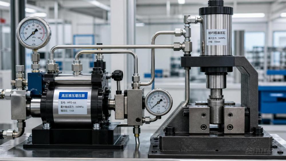
Introduction: High pressure hydraulic intensifiers provide a practical way to multiply output force without installing larger pumps or redesigning an entire fluid power system.
For technical evaluators, the central question is whether an intensifier can meet a localized force requirement without creating unacceptable limits in speed, heat, reliability, or safety.
The short answer is yes, when high pressure is needed at a limited actuator volume rather than continuously across the whole hydraulic circuit.
High pressure hydraulic intensifiers do not create free energy. They exchange flow volume for pressure, allowing a smaller amount of oil to deliver substantially greater force.
What Technical Evaluators Should Confirm First
Before reviewing models or pressure ratios, determine the required cylinder force, stroke length, cycle time, duty cycle, available supply pressure, and usable pump flow.
Those inputs establish whether the application needs a localized pressure booster or whether the existing pump, valve, cylinder, or mechanical arrangement is undersized.
An intensifier is usually most appropriate for clamping, punching, swaging, fixture locking, bolt tensioning, test equipment, and short-stroke pressing operations.
It is less attractive where a large cylinder must travel rapidly under maximum force for long periods, because intensified flow is inherently limited.
Technical evaluations should separate peak force demand from average energy demand. Many machines need very high force only during the final part of a cycle.
For example, a fixture may move quickly at normal system pressure, then require higher pressure only after the workpiece reaches its final clamping position.
In that case, a high pressure hydraulic intensifier can reduce installed pump size while preserving fast approach motion through the conventional circuit.
Evaluators should also confirm whether the equipment requires force multiplication at one station, several independent stations, or every actuator throughout the machine.
A single local station favors an intensifier. Numerous high-demand stations operating together may justify a higher-pressure central hydraulic power unit instead.
How Hydraulic Intensifiers Multiply Pressure
A hydraulic intensifier contains two hydraulically connected pistons with different effective areas. Supply oil acts on the larger piston and drives the smaller high-pressure piston.
Because force equals pressure multiplied by area, the same driving force produces greater pressure when it acts on the smaller output piston area.
The theoretical relationship is straightforward: output pressure equals input pressure multiplied by the ratio between the driving piston area and output piston area.
A three-to-one intensifier supplied at 100 bar can theoretically produce 300 bar output pressure, before accounting for friction, seal drag, and losses.
The output flow follows the opposite relationship. When pressure rises by a factor of three, available output flow decreases to approximately one-third of input flow.
This tradeoff is the defining engineering principle. Intensifiers increase pressure and force, but they cannot deliver both high pressure and high flow without corresponding input power.
In practical systems, manufacturers publish nominal ratios, maximum inlet pressure, maximum output pressure, displacement per stroke, and recommended operating flow ranges.
These data must be reviewed together. Selecting only by pressure ratio can result in slow cycling, unstable operation, excessive heat, or premature seal wear.
Reciprocating intensifiers often use automatic directional switching, allowing repeated strokes that create a continuous, though pulsating, high-pressure output flow.
Some compact units are designed mainly for pressure holding and short volume delivery, while others support repeated production cycles with integrated valving and controls.
Translate Pressure Into the Force the Application Actually Needs
Force calculations should start with the actuator bore area, not with an assumed relationship between pump size and machine capacity.
Cylinder extension force is calculated by multiplying hydraulic pressure by the full piston area. Retraction force uses the smaller annular area after subtracting rod area.
A cylinder with a 50 millimeter bore has approximately 1,963 square millimeters of piston area, so 100 bar produces roughly 19.6 kilonewtons of extension force.
If the process requires 58.9 kilonewtons from the same cylinder, pressure near 300 bar is needed, assuming negligible external losses and appropriate safety allowance.
A three-to-one intensifier could provide that localized pressure from a 100 bar supply, provided its output volume supports the cylinder movement at the required cycle rate.
Design calculations should include friction, seal resistance, tooling losses, changing contact conditions, load variation, and an appropriate margin for material or process variability.
Do not size an intensifier using theoretical pressure alone. The specified output force must remain available at the actual inlet pressure occurring during simultaneous machine operation.
Supply pressure can fall when other axes move, directional valves shift, filters become restricted, oil temperature rises, or the power unit reaches flow limits.
A pressure transducer on the intensifier inlet and another at the high-pressure outlet can verify real operating conditions during a representative production cycle.
This measured approach is particularly important for retrofit projects, where existing hydraulic schematics may not accurately represent accumulated field modifications or current machine loads.
Size for Oil Volume and Cycle Time, Not Just Maximum Pressure
High pressure hydraulic intensifiers are frequently rejected after installation because the required press stroke is slower than expected, even though the pressure rating appears adequate.
The reason is usually insufficient intensified oil volume. The output piston must displace enough fluid to extend the high-force portion of the cylinder stroke.
Calculate the required high-pressure volume by multiplying cylinder area by the distance traveled after the load is contacted or the clamping point is reached.
A long cylinder stroke does not automatically require a large intensifier. A regenerative, fast-approach, or low-pressure sequence can complete most travel before intensification begins.
The pressure booster should serve only the portion of movement requiring elevated force. This often produces a better balance between response time, heat generation, and component cost.
For reciprocating units, compare the manufacturer’s effective output flow with the volume required per cycle, including recharge time and pressure build-up time.
Consider accumulator support where a short, high-flow pressure event is required. An accumulator can store intensified oil and release it faster than the booster alone.
However, accumulators add compliance, safety requirements, precharge maintenance, pressure decay considerations, and stored-energy hazards that must be addressed in the system design.
Cycle estimates should include the time required to charge the high-pressure circuit, move the actuator, hold pressure, vent or return oil, and recover before the next cycle.
When a process requires continuous high-force motion, a larger pump or a separate high-pressure power unit may be more efficient than a small intensifier operating constantly.
Understand Efficiency, Heat, and the Real Limits of Force Multiplication
An intensifier does not reduce the hydraulic power required by the load. It allows available power to be delivered at a higher pressure and lower flow.
Hydraulic input power is approximately pressure multiplied by flow. Any output power remains lower because seals, valve switching, leakage, and fluid friction create losses.
At higher ratios, internal friction and leakage become more influential. The gap between theoretical and achievable pressure can become important near maximum rated output pressure.
High-pressure operation also increases oil heating. Repeated cycling through restrictive passages and pressure control devices converts lost energy into heat within a compact package.
Technical evaluators should request continuous-duty limits, permissible cycles per minute, oil temperature range, viscosity requirements, and maximum allowable backpressure on return lines.
Duty cycle matters more than peak rating in many installations. A unit that performs well during occasional maintenance work may fail quickly in an automated production cell.
Oil cleanliness is equally important. Contamination damages precision sealing surfaces, causes valves to stick, increases internal leakage, and reduces repeatability at elevated pressure.
Review the required filtration level and determine where it applies. Clean oil entering the power unit is not sufficient if contamination can enter the booster branch later.
Pressure spikes must also be considered. Rapid valve closure, decompression events, external load release, and trapped fluid expansion can exceed nominal system pressure limits.
Use properly rated relief valves, pressure-reducing valves, check valves, hoses, fittings, manifolds, and gauges throughout the intensified section, not only at the intensifier outlet.
Integrate the Intensifier Into a Controlled Hydraulic Circuit
A reliable circuit normally includes inlet filtration, isolation capability, pressure measurement, pressure relief protection, check valves, and controlled depressurization for the high-pressure branch.
The circuit should define when intensification starts, how the actuator holds force, how pressure is released, and what happens after an emergency stop or power loss.
For clamping applications, a sequence valve or pressure switch can initiate the booster only after the cylinder reaches the workpiece at normal system pressure.
This arrangement avoids wasting intensified oil during approach travel and reduces the total high-pressure fluid volume that must be controlled and safely relieved.
Check valves are essential where the high-pressure outlet must be retained after the booster stops. Their cracking pressure and flow capacity affect final holding performance.
A pilot-operated check valve may be required when cylinder drift cannot be tolerated. Its pilot ratio and release behavior should be verified against actual system pressure conditions.
Pressure relief protection should be located so that trapped high-pressure oil has a safe discharge path. Never rely solely on a remote low-pressure system relief valve.
Decompression is frequently overlooked. Releasing several hundred bar abruptly can damage seals, create noise, move tooling unexpectedly, or shorten the service life of fittings.
A controlled decompression valve or restricted return path can reduce these effects, although the resulting release time must remain acceptable for the operating sequence.
Where repeatable force is critical, use pressure feedback rather than timing alone. Pressure switches are useful for simple control, while transducers provide better diagnostic visibility.
Selection Criteria Beyond Pressure Ratio
Pressure ratio is an initial screening parameter, but it should never be the only procurement criterion for high pressure hydraulic intensifiers.
Confirm the maximum inlet pressure and maximum outlet pressure separately. A ratio calculation may suggest an output pressure that exceeds the unit’s mechanical rating.
Review output displacement, output flow at the intended inlet flow, switching frequency, pressure intensification time, and minimum oil volume needed for stable operation.
Check seal compatibility with the selected hydraulic fluid, including mineral oil, water glycol, phosphate ester, biodegradable fluids, or fluids used in specialized mobile equipment.
Material selection matters in corrosive, marine, food-adjacent, mining, or outdoor environments. Housing coatings and stainless-steel options may influence long-term availability and maintenance costs.
Mounting orientation, service access, connection type, manifold integration, vibration exposure, and available installation space should be reviewed before finalizing a compact retrofit design.
Evaluate the supplier’s documentation quality. Clear hydraulic schematics, pressure-flow curves, maintenance instructions, spare-part identification, and test evidence reduce integration risk.
For OEM applications, ask about batch consistency, traceability, test procedures, lead times, repairability, warranty boundaries, and availability of equivalent parts across target markets.
Standards and local regulations may influence hose routing, pressure vessel treatment, guarding, noise limits, machinery safety functions, and documentation for stored hydraulic energy.
Technical approval should therefore include both component qualification and system-level review. An intensifier can be correctly specified yet unsafe when installed in an incomplete circuit.
When an Intensifier Is the Right Alternative to a Larger Pump
Choose an intensifier when the machine already has adequate flow for normal motion but lacks pressure for a brief, localized, high-force function.
This approach can avoid replacing the hydraulic power unit, enlarging electric motors, increasing reservoir capacity, and changing multiple valves or distribution lines.
It is especially useful in machine retrofits where space is limited, existing pumps are reliable, and only one process station needs additional pressing or clamping force.
Intensifiers can also reduce central system pressure. Lower-pressure distribution may reduce stress on common lines while reserving high pressure for protected local circuits.
Do not choose an intensifier simply to compensate for a poorly matched actuator. Increasing cylinder bore, revising leverage, or redesigning tooling may solve the problem more efficiently.
A larger pump is often preferable when high pressure and high flow are both required continuously, especially for long-stroke cylinders or multiple simultaneous high-force operations.
A dedicated high-pressure power unit may be preferable where pressure stability, low pulsation, thermal control, or continuous production duty are more important than compactness.
The best decision comes from comparing total system behavior: installed power, cycle time, operating temperature, component ratings, maintenance burden, safety controls, and future expansion needs.
Common Evaluation Errors and How to Avoid Them
A common error is assuming the output pressure will always equal the nominal ratio multiplied by supply pressure. Actual pressure depends on losses and outlet load conditions.
Another error is ignoring the slow speed caused by reduced output flow. Force capability without acceptable cycle time rarely delivers a workable production solution.
Some designs overlook return pressure. Excessive backpressure can reduce effective performance, interfere with switching, and expose seals or housings to unintended loads.
Undersized hoses and fittings can restrict intensified flow, generate heat, and create pressure losses. Every component downstream must be rated for the maximum possible pressure.
Technical teams sometimes treat gauges as adequate monitoring. Permanent transducers and recorded pressure trends provide stronger evidence when diagnosing intermittent force or leakage issues.
Maintenance plans should include inspection for leaks, hose damage, connection loosening, filter condition, abnormal noise, pressure decay, oil contamination, and overheating.
Document the actual high-pressure circuit clearly. Maintenance personnel must know that pressure may remain trapped after the main pump stops or the machine electrical supply is isolated.
Conclusion: Evaluate the Whole Pressure, Flow, and Safety Balance
High pressure hydraulic intensifiers are effective tools for boosting localized force without automatically requiring larger pumps, motors, reservoirs, or broad hydraulic system redesign.
They work best when elevated pressure is needed for a limited oil volume, typically during the final force-producing part of a clamp, press, forming, or test cycle.
For technical evaluators, the decisive factors are not pressure ratio alone. Required force, intensified volume, cycle time, inlet pressure stability, duty cycle, thermal behavior, and safety controls matter equally.
A well-integrated intensifier can provide a compact and economical force upgrade. A poorly evaluated installation can introduce slow cycles, heat, leakage, pressure hazards, and unreliable machine behavior.
Specify the device from measured operating conditions, verify all high-pressure components, and assess the entire circuit as one controlled system before approving the final design.
Related News
- Using Industrial Air Blow Guns to Clear Chips Without Spreading DebrisOct 15, 2026Fluid Power Control Strategist
- Ductile Iron Pipe Valves: Which AWWA Standards Apply to Water Main Projects?Oct 15, 2026Dr. Elias Vance
- Why Vacuum Suction Cups Lose Grip on MDF in Woodworking MachinesOct 15, 2026CNC Kinematics Architect
- Choosing a Variable Displacement Piston Pump Manufacturer: What to VerifyOct 15, 2026Fluid Power Control Strategist
- Parallel vs. Angular Pneumatic Grippers for Confined Assembly StationsOct 15, 2026Fluid Power Control Strategist
- Die Castings vs. Investment Castings: Which Costs Less at Your Production Volume?Oct 14, 2026Foundry Phase-Change Fellow