
How High Pressure Hydraulic Accumulators Control Pressure Spikes and Pump Cycling
A hydraulic power unit that starts every few seconds, a pressure gauge that flicks sharply when a directional valve shifts, or hoses that jump during cylinder deceleration are not minor operating quirks. These signs often point to stored energy being released or demanded too quickly for the pump, lines, and control valves to manage smoothly. Left unresolved, repeated pressure spikes can shorten hose life, loosen fittings, damage seals, fatigue manifolds, and create unstable machine motion.
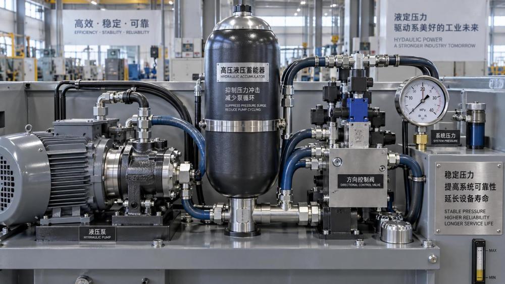
High pressure hydraulic accumulators control these events by storing hydraulic energy in compressed gas and releasing it when the circuit needs flow. Properly selected and charged, an accumulator cushions transient pressure rises, supplies short-duration peak flow, and allows a pressure-compensated or start-stop pump to remain off longer between recharge cycles. It does not replace a correctly set relief valve, nor can it correct severe internal leakage, but it can make a properly designed system far more stable.
What happens during a pressure spike
Hydraulic oil is usually treated as incompressible, but the system around it is not perfectly rigid. Hoses expand slightly, trapped air compresses, valves move, cylinders stop, and pump flow changes. When moving oil is forced to stop or change direction abruptly, its momentum is converted into a rapid pressure increase. This is often called hydraulic shock or fluid hammer.
A common example is a cylinder driving a heavy load toward the end of stroke. If a directional valve closes quickly, the load and moving oil may continue to force flow into a blocked line for a brief moment. The resulting pressure rise can occur much faster than a standard gauge can display. A relief valve may eventually open, but its response time, piping distance, and flow capacity may not be sufficient to prevent the initial peak.
Similar spikes can occur when:
- a large actuator is stopped suddenly;
- a fast solenoid valve shifts between ports;
- a pump outlet check valve closes sharply;
- an emergency shutoff blocks a flowing line;
- a long pipe run carries flow to a remote valve bank;
- an overrunning load drives a cylinder or motor faster than commanded.
The highest risk is not always the normal operating pressure. A circuit may operate below its nominal setting yet experience brief peaks that exceed the pressure rating of a hose assembly, valve section, sensor, or filter housing. Repeated transient loading is especially damaging because components can be weakened over time even when no immediate rupture occurs.
The accumulator’s role: a controlled elastic volume
Most hydraulic accumulators use a gas, usually dry nitrogen, separated from the hydraulic fluid by a bladder, piston, or diaphragm. As oil enters the accumulator, it compresses the gas. When system pressure falls or the circuit demands extra flow, the compressed gas expands and pushes oil back into the circuit.
This gas volume creates a controlled elastic response. Rather than forcing every sudden flow change through rigid pipework or back through a relief valve, the system can temporarily move oil into or out of the accumulator. The accumulator does not eliminate pressure changes; it reduces their rate and magnitude by accepting or supplying flow during the transient.
For pressure-spike protection, the accumulator must be connected close enough to the source of the transient to react before the pressure wave has travelled through a long section of piping. A small accumulator placed near a fast directional valve can be more effective for local shock suppression than a much larger unit installed at the power unit several metres away.
Accumulator performance depends on the gas relationship between pressure and volume. In simplified form, gas behaviour is expressed as:
P1V1n = P2V2n
Here, pressure rises as gas volume falls. The exponent n varies with how quickly the compression and expansion occur. Fast events tend to be closer to adiabatic behaviour, while slower cycles allow more heat transfer. In practical servicing, the important point is that an accumulator’s usable oil volume is only the volume released between its maximum and minimum working pressures. Nameplate shell volume is not the same as usable hydraulic capacity.
Why pump cycling becomes excessive
In a circuit with a pressure switch, unloading valve, variable-displacement pump, or fixed-displacement pump and accumulator, the pump normally charges the accumulator to an upper pressure limit. The pump then unloads, compensates, or stops. As the machine consumes oil through leakage, valve actuation, clamp holding, pilot demand, or thermal contraction, pressure falls toward a lower restart setting. The pump then recharges the stored volume.
Short pump cycles occur when the available stored oil volume between these two pressure limits is too small, or when the system loses pressure faster than expected. The pump may repeatedly start, stroke, destroke, load, and unload even though the machine is not performing useful work. In electrically driven units, frequent motor starts can add heat and contactor wear. In variable-displacement systems, rapid compensator movement can cause noise, heat, and unstable pressure control.
An accumulator reduces cycling only when it has enough usable volume and the precharge is appropriate for the pressure band. A larger shell alone does not guarantee longer off time. An incorrectly high precharge may leave almost no oil stored at the lower operating pressure. An excessively low precharge can over-compress the bladder or piston at high pressure, reduce gas-side service life, and create poor pressure response.
Precharge is the first value to verify
The nitrogen precharge sets the accumulator’s starting gas pressure before hydraulic oil enters. It strongly affects both shock absorption and energy storage. The correct value depends on the accumulator function, minimum and maximum system pressures, temperature range, mounting orientation, and manufacturer instructions.
For a general energy-storage or pump-cycling application, the precharge is commonly set below the circuit’s minimum working pressure so that the accumulator still contains oil at the lower pressure limit. For pulsation and shock damping, the preferred precharge may be closer to the normal system pressure, depending on the expected pressure fluctuation and response requirement. These are different duties and should not be treated as interchangeable settings.
Precharge must be checked with the hydraulic side fully depressurized and isolated from all trapped pressure. Reading gas pressure while hydraulic pressure remains in the accumulator gives a misleading result and creates a hazardous service condition. Allow the gas temperature to stabilize before making a final judgement, particularly after the machine has been running or after a rapid charge-discharge event.
Only nitrogen should be used. Compressed air introduces oxygen and moisture, increasing fire and corrosion risks. Oxygen must never be used in hydraulic accumulators. Use a suitable charging and gauging assembly, follow the vessel manufacturer’s instructions, and avoid standing directly over the gas valve during adjustment.
A practical way to separate sizing problems from faults
When a system begins cycling too often, do not assume the accumulator is undersized. First determine whether the circuit is losing stored pressure because it is consuming oil, leaking internally, or failing to retain the accumulator charge.
A pressure trend is more useful than a single gauge reading. Observe the pressure at pump cut-out, the pressure at restart or compensator response, the time between cycles, and whether that interval changes with temperature. A cycle that becomes much shorter as oil warms often points toward internal leakage through pumps, valves, cylinders, or rotary actuators. An accumulator may mask this condition temporarily, but it cannot restore a circuit that is bypassing oil continuously.
Accumulator location changes the result
For pump cycling control, the accumulator is often installed on the pressure line near the power unit or near the part of the system that consumes stored energy. For a clamping circuit, placing it near the clamp manifold can provide rapid make-up flow and stabilize holding pressure. For a remote actuator, line volume and pressure drop between the accumulator and the load must be included in the assessment.
For shock control, location is even more critical. Long, narrow lines, restrictive fittings, undersized isolation valves, and restrictive check valves can prevent the accumulator from accepting flow quickly enough. The connection should be sized for the required transient flow and arranged so that the fluid path is direct. A device installed behind a small orifice may be suitable for damping a pulsation, yet too slow to protect against a sharp valve-closing event.
Installation must also allow safe isolation, controlled depressurization, and precharge access. A shutoff valve alone is not enough; trapped pressure must have a defined, safe discharge path. Where an accumulator supports a suspended load, emergency motion, or safety-related function, the circuit must be evaluated for what happens when electrical power, pump flow, or control pressure is lost. Stored hydraulic energy can move an actuator after the prime mover has stopped.
Bladder, piston, and diaphragm units serve different duties
Bladder accumulators respond quickly and are widely used for energy storage, shock absorption, and pulsation control. Their construction is well suited to many mobile and industrial hydraulic circuits, but bladder condition, precharge retention, and fluid compatibility must be monitored.
Piston accumulators can offer larger capacities and are often selected where a defined separation between gas and fluid is required over a broad pressure range. They can be effective for larger energy-storage duties, though piston seal friction, orientation limits for certain designs, and response characteristics should be considered.
Diaphragm accumulators are typically compact and responsive, making them useful for smaller volumes and pressure pulsation control. Their usable volume and serviceability may differ from bladder or piston units. Selection should begin with the actual duty: transient suppression, pump standby capacity, leakage compensation, emergency movement, thermal expansion, or a combination of these.
Service habits that prevent repeat failures
A sound maintenance routine starts with system pressure history rather than accumulator replacement by guesswork. Record cut-in and cut-out pressures, cycle frequency, fluid temperature, relief valve setting, and visible leakage before changing the gas charge. This baseline makes it easier to distinguish a lost precharge from a hydraulic fault.
- Lock out the prime mover and confirm that all hydraulic pressure sources are isolated.
- Discharge pressure through the designed circuit path; never loosen fittings to release stored energy.
- Verify zero pressure on the hydraulic side before attaching a gas charging assembly.
- Inspect the accumulator body, mounting clamps, fluid connection, gas valve cap, hose condition, and nearby fittings for damage or leakage.
- Measure the nitrogen precharge after temperature stabilizes, then compare it with the equipment specification for that duty.
- Recharge slowly if required, reassemble protective caps, and return the circuit to service while monitoring pressure behaviour.
Repeated precharge loss is not a normal adjustment issue. It can indicate gas-valve leakage, permeation over an extended service interval, or internal separator damage. Oil escaping from the gas side, a sudden inability to retain charge, or abnormal accumulator noise warrants removal from service and inspection under the applicable manufacturer procedure. Pressure vessels, charging equipment, and local inspection requirements may also impose specific service controls.
When pressure spikes and pump cycling are evaluated together, the best result usually comes from treating the accumulator as part of the whole circuit: pump controls establish the pressure band, valves determine transient flow paths, plumbing determines response speed, and the accumulator provides the stored volume. Correct precharge, suitable capacity, direct placement, and disciplined pressure testing turn high pressure hydraulic accumulators from passive vessels into effective protection for the system.
Related News
- How to Assess a Rigid Coupling Supplier for Bore Accuracy and Traceable QualityOct 08, 2026Tribology & Kinematics Expert
- Titanium Alloys Compared: Balancing Strength, Corrosion Resistance, and MachinabilityOct 08, 2026CNC Kinematics Architect
- Where Ductile Iron Dismantling Joints Reduce Alignment Risk in Water PipelinesOct 08, 2026Pipeline Metallurgy Scientist
- Selecting a Precision Bearing Sleeve: Fits, Runout, and Material ChoicesOct 08, 2026Tribology & Kinematics Expert
- Face Milling Cutters: How Insert Geometry Affects Finish on Steel and AluminumOct 08, 2026CNC Kinematics Architect
- Single-Acting Cylinders for Clamping: Stroke, Force, and Return Spring ConsiderationsOct 07, 2026Fluid Power Control Strategist