
High-Pressure Hydraulic Seal Kits: How to Prevent Leakage During Cylinder Repairs
A hydraulic cylinder that leaks shortly after repair rarely fails because of one bad seal alone. Repeat leakage is more often the result of a mismatch between the seal kit, the cylinder’s actual condition, and the repair method. A high-pressure cylinder can hold pressure with an unsuitable seal for a short period, then begin bypassing internally, weeping at the rod, or damaging the new components as soon as load, heat, side force, or contamination returns.
The practical objective of a cylinder repair is not simply to replace soft parts. It is to restore a controlled sealing interface between the rod, piston, gland, barrel, and hydraulic fluid. High-pressure hydraulic seal kits can do this reliably only when the technician verifies the failure mode, matches materials and profiles to service conditions, and protects every sealing surface during disassembly and assembly.
Find the leakage path before opening the cylinder
External leakage and internal bypass require different diagnosis. Replacing a complete kit without identifying the path can conceal the real problem until the cylinder returns to service.
Rod-end leakage usually appears as an oil film, drip, or wet accumulation around the gland, wiper, rod surface, or mounting area. The rod seal is an obvious suspect, but it is not automatically the root cause. A scored rod, corrosion pit, bent rod, excessive bearing clearance, incorrect gland tightening, or a damaged wiper can quickly destroy a replacement rod seal.
Internal leakage is less visible. The cylinder may drift under load, lose holding force, move unevenly, or require more pump flow to maintain function. In a double-acting cylinder, piston-seal bypass allows fluid to pass from the pressurized chamber to the opposite chamber. A system-level pressure test may not isolate this condition because valve leakage, pump wear, and cylinder bypass can produce similar operating symptoms. The cylinder should be evaluated in the context of the circuit before the piston seal is blamed.
Leakage around a gland outside diameter, end cap, port adapter, or cylinder head connection may be caused by static sealing failure rather than a rod or piston seal problem. An O-ring may have been cut on installation, extruded through an excessive clearance gap, flattened by compression set, or chemically damaged by incompatible fluid. A high-pressure hydraulic seal kit is only effective when each included component is used in the correct groove and orientation.
Before removal, record the cylinder function, working pressure, fluid type, temperature exposure, load direction, cycle pattern, and visible symptoms. These details matter because a seal that performs in a moderate-pressure, clean indoor power unit may fail quickly in a mobile cylinder exposed to shock loads, abrasive dust, cold starts, and rod side loading.
A seal kit is a system of parts, not a collection of interchangeable rings
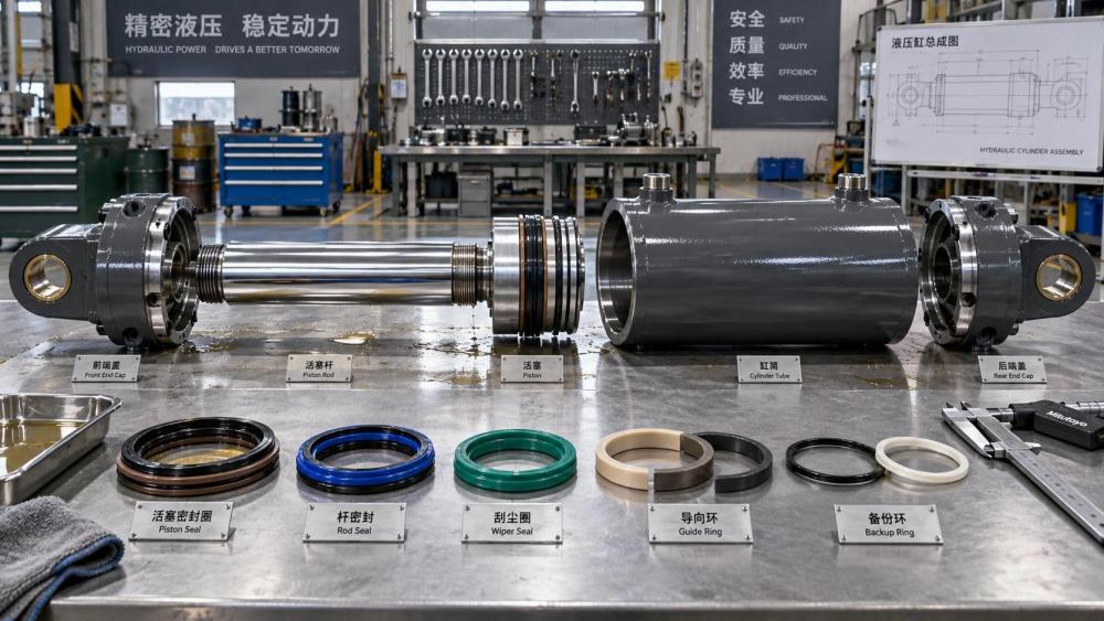
High-pressure hydraulic seal kits commonly contain a piston seal, rod seal, wiper or scraper, guide rings, static O-rings, backup rings, and sometimes wear rings or buffer seals. Their functions overlap, but they should not be substituted casually.
The piston seal separates the pressure chambers. Its ability to hold pressure depends on the seal design, barrel condition, groove dimensions, fluid viscosity, and radial clearance. The rod seal prevents pressurized fluid from escaping along the rod. The wiper excludes dirt, moisture, and abrasive particles from entering the cylinder during retraction. Guide rings keep the rod and piston centered and prevent metal-to-metal contact. Backup rings support elastomeric seals where pressure could force the material into a clearance gap.
A repair can fail when attention is focused only on the visibly damaged rod seal. For example, worn guide rings allow increased lateral movement. That movement loads one side of the rod seal lip, damages the oil film, and creates uneven wear. Replacing the rod seal without correcting the guidance problem may stop leakage briefly but does not restore the cylinder’s alignment control.
Likewise, an O-ring that appears serviceable may no longer be appropriate if the repair includes a change in operating pressure, fluid formulation, or groove condition. Reusing old static seals is especially risky where dismantling has already disturbed compression, surface contact, or backup-ring position.
Match seal material to fluid, temperature, and pressure behavior
Material selection should begin with the fluid actually in service, not the fluid assumed from the equipment manual. Mixed fluids, replacement oils, biodegradable fluids, water-glycol fluids, and fluids containing different additive packages can alter seal compatibility. If the equipment history is uncertain, identifying the fluid before assembly is more valuable than selecting a kit based only on cylinder dimensions.
Nitrile rubber, commonly identified as NBR, is widely used with mineral oil hydraulic fluids and is suitable for many standard service conditions. It is not a universal answer. Elevated temperature, ozone exposure, certain synthetic fluids, and chemical environments can require other materials. Fluorocarbon elastomers such as FKM can offer stronger high-temperature and chemical resistance in compatible applications, but they are not automatically suitable for all low-temperature conditions or fluid types.
Polyurethane is frequently used in high-performance rod and piston seals because it provides good wear resistance and extrusion resistance. Its behavior depends on formulation and application. It can be effective in demanding mobile equipment, but it may not be the preferred choice where temperature, fluid chemistry, or low-temperature flexibility exceeds its service range. PTFE-based sealing elements offer low friction and chemical resistance, often with an energizer to maintain contact force, but they require correct groove geometry and careful installation.
Pressure rating must be interpreted as a system condition, not merely the nominal setting of a relief valve. Pressure spikes from rapid directional-valve shifts, inertial loads, blocked flow, or external shock can be more severe for seals than stable operating pressure. In these conditions, backup rings, anti-extrusion features, proper hardness, and controlled diametral clearance become critical. A seal may survive normal pressure but extrude during repeated transient events.
Inspect hard parts with the same discipline used for soft parts
Seals work against machined surfaces. No replacement kit can compensate for a rod with deep scoring, lifted chrome, pitting within the seal travel area, or a barrel with severe scratches and corrosion. A new lip seal may initially bridge minor imperfections, but pressure cycling can tear the lip or create a leakage channel around the damaged surface.
Rod inspection should cover the entire stroke length, especially the region that passes through the rod seal and wiper. A visual check alone is insufficient for borderline damage. Run a clean fingernail lightly across suspicious marks: a defect that catches may be significant enough to damage a sealing lip. This is not a substitute for dimensional inspection, but it is a useful screening method during strip-down.
Check for rod bending where side loading, collision, or mounting failure is possible. A slightly bent rod can create a recurring one-sided leak pattern and accelerated guide-ring wear. The gland bore, piston grooves, barrel bore, and threads also require inspection. Burrs at ports, threads, retaining-ring grooves, or cross-holes are particularly dangerous because they can cut a seal during assembly before the cylinder is ever pressurized.
Measure critical dimensions against the cylinder drawing or verified component specifications where available. Groove width, groove depth, rod diameter, bore diameter, and extrusion gaps determine whether a seal is properly energized and supported. A kit matched only by nominal cylinder bore and rod size may not fit a nonstandard gland, a modified cylinder, or a cylinder with prior machining work.
Surface finish is equally important. A highly rough surface can abrade seal lips; an overly smooth or improperly finished surface may fail to retain the controlled lubricant film needed for stable dynamic sealing. The appropriate finish depends on seal design and manufacturer guidance, so re-polishing or re-chroming should not be treated as a generic corrective action without confirming the required finish range.
Cleanliness controls both immediate and delayed leakage
Hydraulic contamination is not limited to visible dirt. Fine metallic particles, cured coating fragments, abrasive dust, shop rag fibers, and degraded seal material can lodge under a lip seal or score a running surface. A cylinder assembled on an unclean bench may pass a short function check yet fail after contamination circulates through the system.
Clean the cylinder barrel, rod, gland, piston, and all reusable hardware with a fluid-compatible cleaning process. Avoid aggressive tools that leave embedded abrasive particles or alter sealing surfaces. Blow-drying with compressed air requires caution: unfiltered shop air can introduce moisture and particles, while high-pressure air can propel debris into grooves and internal passages.
Cleanliness must continue through assembly. Keep new seals in their packaging until needed. Separate components by cylinder position so that a rod seal, buffer seal, and wiper are not confused. Do not lay seals directly on contaminated work surfaces. Lubricate with a clean fluid compatible with both the hydraulic system and seal material; an unsuitable grease can swell elastomers, block small passages, or attract contaminants.
Installation errors that create leaks before startup
Seal orientation is one of the most frequent causes of immediate failure. Pressure-energized lips generally face the pressure side, but the exact arrangement depends on whether the component is a rod seal, piston seal, buffer seal, wiper, or symmetrical seal. A seal profile should never be installed based on appearance alone. Confirm orientation using the kit documentation, cylinder drawing, or the seal manufacturer’s technical data.
Stretching and twisting can permanently damage seals. PTFE elements, U-cups, energized seals, and tight-fitting rod seals may need purpose-made installation tools, sizing sleeves, tapered cones, or split tools. Sharp screwdrivers, picks, and improvised hooks often nick the sealing edge or leave a twist that becomes visible only after cycling.
Protect seals from every sharp transition. Cover threads, keyways, grooves, ports, and cross-holes with an installation sleeve or smooth protective film before passing a seal over them. Remove burrs without changing the functional geometry of the component. A seal that must be forced over a sharp edge should not be expected to survive high-pressure service.
Backup rings deserve particular attention. Some are directional; others are installed on the low-pressure side of the O-ring to resist extrusion toward that side. Split backup rings may be supplied in a specific configuration. Incorrect placement can allow extrusion even when the primary O-ring material is otherwise correct.
After fitting, inspect each seal for rolling, twisting, pinching, or uneven seating. Guide rings should sit fully in their grooves without overlap unless their design specifically requires a scarf or step joint. Confirm that the piston and gland can enter the barrel without excessive force. High assembly force is a warning sign, not evidence of a tight seal.
Commission the repaired cylinder gradually
A repaired cylinder should not be sent directly to maximum pressure. Initial operation should use low pressure and controlled movement to confirm correct extension, retraction, port connection, and absence of immediate external leakage. Slow cycling also gives seals time to seat and distribute lubricant across the dynamic surfaces.
Increase pressure in stages while observing the rod gland, end-cap joints, ports, and hose connections. Check cylinder behavior under the load condition that originally exposed the problem. For holding cylinders, monitor drift only after isolating other circuit leak paths as far as practical. A cylinder that passes a no-load stroke test may still bypass under sustained load.
Monitor fluid condition after repair. If the removed seals show abrasive scoring, embedded particles, hardening, blistering, or extrusion damage, the cylinder repair should trigger a broader inspection of filtration, breather condition, reservoir cleanliness, hose deterioration, pressure settings, and mechanical alignment. Replacing seals without correcting the cause converts a repair into a repeat maintenance event.
When a seal kit is not the appropriate repair
Seal replacement is not a cure for structural or dimensional defects. Rod re-chroming, rod replacement, barrel honing, gland replacement, piston repair, or complete cylinder replacement may be necessary when damage exceeds the capability of the seals to compensate. Continuing with a kit-only repair in such conditions can create safety risks, repeat downtime, and contamination of the wider hydraulic circuit.
The most reliable high-pressure hydraulic seal kit is therefore not necessarily the kit with the hardest material or the most aggressive profile. It is the one that matches verified dimensions, real fluid conditions, pressure transients, temperature, surface condition, and cylinder motion. Leakage prevention begins with diagnosis, but it is secured by disciplined inspection, clean assembly, correct orientation, and controlled recommissioning.
Related News
- Using Industrial Air Blow Guns to Clear Chips Without Spreading DebrisOct 15, 2026Fluid Power Control Strategist
- Ductile Iron Pipe Valves: Which AWWA Standards Apply to Water Main Projects?Oct 15, 2026Dr. Elias Vance
- Why Vacuum Suction Cups Lose Grip on MDF in Woodworking MachinesOct 15, 2026CNC Kinematics Architect
- Choosing a Variable Displacement Piston Pump Manufacturer: What to VerifyOct 15, 2026Fluid Power Control Strategist
- Parallel vs. Angular Pneumatic Grippers for Confined Assembly StationsOct 15, 2026Fluid Power Control Strategist
- Die Castings vs. Investment Castings: Which Costs Less at Your Production Volume?Oct 14, 2026Foundry Phase-Change Fellow