
High Hydraulic Pressure Intensifier Sizing: Flow, Ratio, and Duty Cycle
A high hydraulic pressure intensifier should be sized from the required output event, not from its maximum advertised pressure ratio. The central question is whether the unit can deliver enough oil volume at the required pressure, for the required time, without exceeding the available inlet flow, overheating the circuit, or overstressing downstream components.
This matters because an intensifier trades flow for pressure. A large ratio can produce impressive pressure on paper, but it also reduces output flow and can create a slow, heat-prone system if the inlet supply or duty cycle is not matched to the application. For clamping, bolt tensioning, hydrostatic testing, press tooling, emergency actuation, and other intermittent high-pressure functions, the correct choice is usually the smallest ratio and capacity that meet the real pressure-and-volume requirement with reasonable margin.
Start with the output requirement, not the pressure ratio
Before comparing a high hydraulic pressure intensifier, define what the high-pressure side must actually do. “Need high pressure” is not enough. A technical specification should identify the target working pressure, the fluid volume required per cycle, the time allowed to build pressure, the number of cycles, and whether pressure must be held after the movement is complete.
These conditions lead to very different equipment choices. A small fixture circuit may need only a modest volume to seat several clamps and then hold pressure for a long period. A forming or test application may need continuous replenishment because internal leakage, cylinder movement, or controlled pressurization consumes flow. An intensifier that works well for occasional clamping may be unsuitable for a repeated production cycle, even when its peak pressure rating is sufficient.
Separate the requirement into three parts:
- Pressure: the pressure needed at the actuator, tool, or test vessel after normal losses in valves, hoses, fittings, filters, and manifolds.
- Volume: the oil volume needed to fill lines, extend a high-pressure cylinder stroke, compress the system, and make up expected leakage.
- Time: the permitted pressure-rise time and the duration for which the system remains pressurized.
A common sizing error is to use actuator force alone. Force establishes the required pressure only after the effective piston area is known. It does not reveal the oil volume or the response time required. Both are essential to sizing an intensifier.
How ratio changes pressure and available flow
A hydraulic intensifier uses a larger low-pressure driving area to move a smaller high-pressure pumping area. In simplified form, the pressure ratio is determined by the relationship between those effective areas. If friction, seal drag, and internal losses are ignored, output pressure is approximately inlet pressure multiplied by the area ratio.
Real systems require a more cautious approach. Seal friction, switching losses, fluid viscosity, return-side backpressure, and pressure drop through the inlet circuit reduce the practical pressure available at the outlet. The useful question is not “what is the theoretical multiplication?” but “what output pressure can be maintained at the expected inlet pressure and flow condition?”
The same area relationship affects flow in the opposite direction. As pressure is intensified, output flow decreases roughly in proportion to the ratio. A 10:1 intensifier supplied by a given inlet flow cannot provide that same flow at its outlet. It produces a much smaller high-pressure flow, before normal volumetric losses are considered.
Select the lowest practical ratio that produces the required working pressure from the lowest credible inlet pressure. This gives more usable output flow than an oversized ratio and generally reduces cycling frequency. Margin is still needed, but it should cover predictable losses and inlet variation rather than become an arbitrary multiplier.
Calculate flow from the required pressure-rise time
Output flow should be based on the volume that must be pressurized within the permitted time. That volume includes actuator displacement, pipe and hose filling, manifold cavities, and the small but meaningful fluid compression that occurs at high pressure. Long small-bore lines can be especially misleading: their physical volume may appear modest, yet their expansion and the compression of the contained oil can slow the final stage of pressurization.
For a cylinder, displacement volume is calculated from effective piston area multiplied by stroke. The effective area must match the direction of motion. Extension uses the full bore area; retraction uses the annular area after deducting the rod. For multiple actuators, add the volumes that move simultaneously rather than summing every actuator in the machine.
Required average high-pressure flow is then the total demand volume divided by the desired pressure-rise time. This is an initial estimate, not a final selection value. The intensifier’s published delivery rate normally depends on inlet pressure, output pressure, fluid condition, and operating frequency. Its output also becomes lower as the pressure differential rises. A unit should therefore be evaluated at the intended operating point, not at a no-load or peak-flow catalog figure.
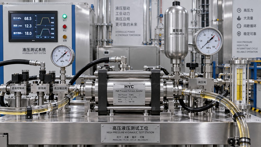
Where the high-pressure demand is a short pulse, an accumulator can change the design substantially. The intensifier charges the accumulator over a longer interval, while the accumulator supplies the brief high-flow event. This can be effective for clamp closing, short test fills, or intermittent tool functions. It does not remove the need to examine heat and energy balance; it shifts when the energy is supplied.
Duty cycle is a thermal and reliability calculation
Duty cycle is often written as operating time divided by total cycle time, but the useful engineering view is more specific: how long is the intensifier actively stroking at high differential pressure, how often does that occur, and what happens while the system is holding pressure?
An intensifier can be idle while a clamped tool remains pressurized, provided the circuit is properly isolated and leakage is low. That condition is very different from an intensifier repeatedly cycling to compensate for leakage or to maintain a live high-pressure function. Frequent cycling produces heat through throttling, internal leakage, fluid shear, and mechanical friction. It also increases seal, check-valve, and switching-component wear.
Continuous or near-continuous high-pressure operation deserves particular scrutiny. An intensifier may be technically capable of producing the pressure, yet remain a poor system choice if it must run most of the shift. In that situation, a purpose-designed high-pressure pump, a different actuator area, a revised process sequence, or stored hydraulic energy may provide a more stable solution.
Evaluate duty cycle using the real machine schedule, including start-up, failed cycles, pressure-hold periods, and warm fluid conditions. The thermal capacity of the reservoir, cooler, pump, and piping must be considered as a system. Temperature control is not merely an oil-life issue; changing viscosity also affects leakage, response, and the ability of the intensifier to reach pressure consistently.
Check the inlet circuit before blaming the intensifier
The inlet side determines whether the pressure ratio is usable. An intensifier supplied by a small pump, restrictive directional valve, undersized hose, contaminated filter, or shared circuit can see inlet pressure collapse when it begins to stroke. The resulting output pressure may be unstable, slow to build, or unable to reach the intended setting.
Measure or calculate inlet pressure at the intensifier inlet during the demanding portion of the cycle. Nominal pump pressure at the power unit is not a substitute. Pressure losses upstream become more important when a high ratio multiplies the effect of an inlet-pressure reduction.
Return flow also needs attention. Excess return-side backpressure reduces the effective driving force and may affect seals or switching behavior. Return plumbing should be sized and routed to avoid unnecessary restriction, and the reservoir arrangement should support clean, deaerated fluid. Entrained air causes delayed response, pressure instability, noise, and additional heat, particularly in circuits with rapid pressure transitions.
Pressure rating is a system property
Every component exposed to the intensified side must be suitable for the expected pressure, including transients. That includes cylinders, valves, gauges, transducers, hoses, fittings, couplings, manifolds, test connections, and any fixture or tooling body that contains pressure. A high-pressure hose connected to a lower-rated fitting does not create a high-pressure assembly.
Pressure relief and isolation strategy require the same level of attention. A relief device protects against an overpressure condition only if it is located and connected so that it can see the pressure source it is intended to control. Check valves can isolate portions of a circuit; trapped fluid can then rise in pressure from thermal expansion or external loading even after the intensifier stops. A suitable pressure-release path and controlled depressurization method should be part of the design, especially where personnel may disconnect a line or service a fixture.
For test circuits, distinguish between normal working pressure, proof or test pressure, and any transient generated by rapid valve movement or a suddenly blocked flow path. Selection based only on normal pressure leaves little room for the conditions that tend to damage components.
Choose the layout that matches the operating pattern
A compact in-line intensifier is often appropriate when a machine already has a moderate-pressure hydraulic supply and only one local function requires a higher pressure. It can reduce the need for a separate high-pressure power unit, provided the high-pressure volume is limited and operation is intermittent.
A dedicated intensifier circuit with accumulator support is more suitable when the high-pressure event is brief but must happen quickly. The upstream pump can replenish stored energy between events, while the downstream circuit receives a faster burst of flow. The accumulator must be selected around usable fluid volume across its pressure range, not simply its nominal shell size.
When the process requires sustained high-pressure flow, the decision should be challenged early. A high hydraulic pressure intensifier may still be part of the solution, but it should not be assumed to be the primary continuous-flow source. The energy loss inherent in pressure multiplication becomes more significant as operating time increases.
A practical sizing sequence
- Define the required outlet pressure at the load, including known line and valve losses.
- Determine the lowest inlet pressure available while the intensifier is operating, rather than using a nominal pump value.
- Select a preliminary ratio that meets the pressure requirement with operating margin, avoiding a higher ratio unless it is needed.
- Calculate the high-pressure volume needed for actuator movement, line fill, compression, and expected make-up flow.
- Set the maximum permitted pressure-rise time, then compare it with the intensifier’s delivery at the intended pressure condition.
- Map the actual operating cycle to estimate active run time, hold time, repeat rate, and thermal exposure.
- Verify ratings, pressure control, depressurization, fluid cleanliness, return conditions, and compatibility across the entire intensified circuit.
Supplier data is most useful when the inquiry includes these operating details. Asking only for a ratio and maximum pressure usually produces a broad product match rather than a defensible system selection. IMPE’s hydraulic and pneumatic equipment coverage is relevant here because intensifier sizing is inseparable from pump capacity, valves, hoses, accumulators, actuator design, contamination control, and the integrity of the full fluid-power assembly.
Common selection mistakes
Specifying maximum pressure as the normal operating point. Running continuously at the edge of a unit’s pressure capability leaves less tolerance for changing oil temperature, inlet losses, and wear. A workable design considers the normal condition separately from occasional peaks.
Ignoring pressure hold behavior. If pressure decays rapidly after the intensifier stops, the issue may be internal cylinder leakage, a check valve that does not seal reliably, a thermal change, or an external leak. Increasing the intensifier ratio does not correct the root cause.
Assuming high pressure means high force without checking mechanics. Cylinder mounting, fixture stiffness, tool contact area, and structural load path can limit the usable force before hydraulic pressure does. The pressure source and the mechanical assembly must be evaluated together.
Using small tubing to simplify installation. A line that is acceptable at lower pressure may have unsuitable pressure capacity, excessive pressure drop, or an inappropriate connection method at the intensified side. High-pressure plumbing requires deliberate selection of materials, joining methods, support, and inspection access.
What to confirm before releasing the design
The final review should produce a clear operating envelope: inlet pressure range, expected inlet flow, required outlet pressure, high-pressure volume per event, permitted build time, active duty cycle, fluid type and temperature range, return condition, and all downstream pressure ratings. It should also document the pressure-control and safe-release arrangement.
That record does more than support procurement. It makes later troubleshooting faster. When a system becomes slow, runs hot, or fails to maintain pressure, the team can compare actual values with the conditions used for sizing instead of treating the intensifier as an isolated component.
A properly sized intensifier is not necessarily the one with the highest ratio or highest headline pressure. It is the one that supplies the required high-pressure volume at the required rate, within the thermal and mechanical limits of a complete hydraulic system.
Related News
- How to Assess a Rigid Coupling Supplier for Bore Accuracy and Traceable QualityOct 08, 2026Tribology & Kinematics Expert
- Titanium Alloys Compared: Balancing Strength, Corrosion Resistance, and MachinabilityOct 08, 2026CNC Kinematics Architect
- Where Ductile Iron Dismantling Joints Reduce Alignment Risk in Water PipelinesOct 08, 2026Pipeline Metallurgy Scientist
- Selecting a Precision Bearing Sleeve: Fits, Runout, and Material ChoicesOct 08, 2026Tribology & Kinematics Expert
- Face Milling Cutters: How Insert Geometry Affects Finish on Steel and AluminumOct 08, 2026CNC Kinematics Architect
- Single-Acting Cylinders for Clamping: Stroke, Force, and Return Spring ConsiderationsOct 07, 2026Fluid Power Control Strategist