
Do Hydraulic Gear Pumps Reliably Handle Variable Flow in Treatment Plants?
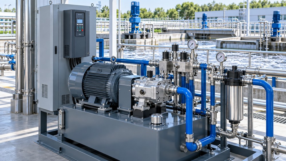
Hydraulic gear pumps can operate reliably in treatment plants, but they do not inherently provide variable displacement. Their output is essentially fixed per shaft revolution, so reliable variable-flow operation depends less on the pump alone than on the drive method, hydraulic circuit design, pressure-control arrangement, oil cleanliness, and the actual duty cycle.
This distinction matters because “variable flow” can describe two very different requirements. A treatment plant may need a hydraulic system to move an actuator at different speeds, modulate a valve, operate a sludge-handling machine intermittently, or maintain pressure while demand changes. In those cases, a gear pump can be a sound choice. If the requirement is to continuously match pump output to widely changing demand with low energy loss and limited heat generation, a fixed-displacement gear pump may be the wrong primary solution unless it is paired with suitable controls.
It is also important not to confuse a hydraulic gear pump with a process pump. Gear pumps in this context normally circulate hydraulic oil to power cylinders, hydraulic motors, gates, rakes, presses, compactors, and other equipment. They are generally not selected to pump raw water, wastewater, sludge, or chemically aggressive treatment media. The fluid being controlled is hydraulic oil; the process equipment is what ultimately affects water or wastewater flow.
What a gear pump can and cannot do
An external gear pump transfers a fixed geometric volume of oil for each revolution of its gears. Actual delivered flow is influenced by rotational speed, internal leakage, oil viscosity, suction conditions, and wear, but the basic relationship remains straightforward: increasing shaft speed increases flow, while decreasing speed reduces flow.
That makes gear pumps robust and predictable in systems with a fairly stable pressure range and intermittent or moderate changes in demand. Their construction is comparatively simple, compact, and widely understood by maintenance teams. For many hydraulic power units, that simplicity is valuable: there are fewer precision moving elements than in many variable-displacement piston pump designs, and service requirements can be manageable when the fluid is kept clean.
The limitation is that a standard gear pump cannot independently reduce its displacement when system demand falls. If an electric motor continues to drive the pump at constant speed, the pump continues producing approximately the same flow. Excess flow must then be directed elsewhere, often through a relief valve, unloading valve, bypass path, or control valve. This arrangement can work mechanically, but it may waste energy as heat.
Reliability therefore has two dimensions:
- Mechanical reliability: whether the pump can survive the pressure, speed, contamination level, and temperature conditions.
- System reliability: whether the circuit can regulate changing demand without overheating oil, causing unstable motion, creating pressure spikes, or cycling components excessively.
A gear pump may be mechanically durable while still being a poor system choice for a highly variable, continuous-load application.
When variable flow is a reasonable use case
Gear pumps are often suitable where variable flow is needed in steps, during short operating periods, or through predictable machine sequences. Examples include screen rakes that operate only when differential level or timer logic calls for cleaning, hydraulic gates that move at controlled but intermittent speeds, compactor cylinders, dosing skid actuators, and maintenance equipment with limited operating hours.
In these applications, the key question is not whether the pump itself is variable displacement. It is whether the circuit can provide the required actuator speed and force without placing excessive thermal or pressure stress on the power unit.
A variable-frequency drive (VFD) on the electric motor is often the most direct way to vary gear-pump output. Reducing motor speed reduces pump flow, which can lower throttling losses and reduce heat compared with a constant-speed pump sending surplus oil across a relief valve. However, a VFD does not eliminate the need for pressure control. It must be coordinated with the actuator load, minimum motor speed, pump lubrication needs, response requirements, and system pressure settings.
For applications that require several discrete operating speeds, a VFD or multiple pump sections may be practical. For example, a system might run at low speed during a holding condition, increase flow for actuator movement, then unload or stop when the cylinder reaches its position. This is generally more efficient than continuously circulating full pump flow at high pressure.
Where fixed-displacement gear pumps become inefficient
The difficulty arises when a treatment plant requires sustained flow modulation over a broad range while the hydraulic system remains pressurized for long periods. A typical example is a circuit where a proportional valve continuously restricts flow to control actuator speed, while a constant-speed gear pump supplies more flow than the actuator needs.
The difference between produced flow and useful flow becomes heat. The more severe the restriction and the higher the pressure drop, the more energy is converted into heat within the hydraulic oil. An oil cooler can remove heat, but it does not recover the energy already lost. It also adds equipment, maintenance needs, and another potential point of failure.
Throttling is not automatically unacceptable. It can be reasonable for short-duration motion, low-power circuits, or systems where fine control is needed only occasionally. But it deserves close scrutiny when the system spends many hours operating at partial demand. In that duty pattern, variable-displacement piston pumps, load-sensing circuits, servo-driven power units, or other demand-matched designs may offer better lifecycle performance.
Pressure-compensated variable-displacement pumps are designed to reduce delivered flow as pressure rises toward a set value. Load-sensing designs can adjust output more closely to what downstream functions require. These designs are more complex and can be more sensitive to contamination and commissioning quality, but they address the core inefficiency of a fixed-displacement pump running constantly against changing demand.
Pressure stability matters more than nominal flow
A common selection error is to focus on a gear pump’s catalog flow rating without examining how flow behaves at the operating pressure. Internal leakage increases as pressure differential rises and as clearances increase with wear. Oil temperature also affects leakage because viscosity changes significantly with temperature.
As a result, a pump that appears adequate at low pressure may provide less effective flow when an actuator encounters its highest load. A gate cylinder, dewatering mechanism, or compaction device may slow down under load even though the pump’s nominal flow rating looked sufficient during selection.
Pressure ripple is another consideration. Gear pumps produce pulsating flow because of gear meshing and trapped fluid volume changes. In many industrial hydraulic applications, the resulting ripple is acceptable. In circuits requiring very smooth low-speed motion or highly stable proportional control, it can complicate tuning and contribute to vibration, noise, or actuator stick-slip.
The issue is not that gear pumps are inherently unreliable; it is that pump pulsation, hose elasticity, valve characteristics, trapped air, and load variation can interact. A long hydraulic line to a remote treatment structure may amplify these effects. Accumulators, properly sized lines, correctly located pressure sensors, suitable control-valve selection, and careful commissioning can improve behavior, but they should be considered as part of the original design rather than corrective additions after instability appears.
Fluid cleanliness is a reliability boundary
In treatment plants, hydraulic power units may be located in humid areas, near washdown operations, outdoors, or beside equipment exposed to dust, grit, and corrosive atmospheres. These conditions do not automatically prevent use of gear pumps, but they make contamination control central to reliability.
Gear pumps tolerate many industrial duties well, yet abrasive particles can score gear faces, wear bushings and housing surfaces, and increase internal leakage. Water contamination can reduce lubricant film strength, promote corrosion, and accelerate degradation of the hydraulic fluid. Once clearances enlarge, the pump may still turn normally but lose volumetric efficiency, particularly when the circuit requires pressure.
A credible reliability assessment should therefore examine the whole oil-management arrangement:
- reservoir design and effective separation of return flow from the suction zone;
- suction line size, inlet restrictions, and whether the pump receives adequate inlet pressure;
- return-line and pressure-line filtration appropriate to component sensitivity;
- breather selection, especially where humidity or washdown exposure is present;
- water-ingress controls and the condition of cylinder rods, seals, and hose connections;
- oil temperature monitoring and cooling capacity for the real duty cycle;
- fluid sampling practices where downtime consequences justify condition monitoring.
Filter placement requires judgment. A severely restricted suction strainer can cause inlet starvation, particularly when oil is cold or viscous. Cavitation and aeration can then damage the pump and make flow control erratic. Fine filtration is often more effectively applied in return or pressure lines, with the precise arrangement determined by the pump manufacturer’s limits and the circuit’s contamination target.
Suction conditions can determine pump life
Gear pumps are positive-displacement devices. They cannot compensate for a poorly designed inlet line. If the suction pipe is undersized, excessively long, routed with unnecessary bends, fitted with restrictive valves, or supplied from a reservoir with inadequate head, the pump may operate with insufficient inlet pressure.
Symptoms can include noise, vibration, foamy oil, unstable actuator motion, reduced output, rising temperature, and premature wear. These symptoms are sometimes misdiagnosed as a failing pump when the root cause lies upstream at the reservoir, breather, suction line, or fluid condition.
Cold-start performance needs particular attention. Hydraulic oil has higher viscosity at low temperature, increasing suction losses and motor torque demand. A pump-and-motor combination that performs acceptably at normal temperature can struggle during startup. If the system must operate outdoors or in an unheated building, oil-grade selection, startup logic, reservoir heating where justified, and minimum-temperature operating limits should be addressed before equipment is specified.
Control architecture determines whether the system is sensible
There is no universal answer to whether a gear pump “handles” variable flow. The answer changes with the control method.
A VFD-controlled gear pump has limits that should not be overlooked. At very low speed, actual performance may become less predictable because leakage becomes a greater portion of theoretical flow. Cooling and lubrication arrangements may also differ from conditions at rated speed. At high speed, inlet conditions, fluid viscosity, and allowable shaft speed set limits. The usable operating range is not simply the motor’s speed range; it is the range within which the pump, motor, coupling, fluid, and suction arrangement can operate safely.
Do not select only from maximum pressure and displacement
For a treatment-plant hydraulic unit, pump displacement and maximum pressure are necessary starting points, not a complete selection basis. The required output should be derived from actuator area, desired movement speed, load profile, simultaneous functions, expected leakage, and any reserve requirement. Pressure should be based on the highest credible working load plus a considered allowance, not merely the relief-valve setting.
The duty cycle is equally important. A pump used for a brief gate adjustment once per day faces a very different thermal and wear profile from a pump running throughout a shift while regulating a continuous process. The same nominal pump can be entirely suitable in the first case and economically weak in the second.
Compatibility between hydraulic fluid and seals, hose materials, coatings, and ambient conditions must also be confirmed. Where biodegradable hydraulic fluids are required because of environmental exposure, viscosity behavior, material compatibility, and manufacturer approval need specific review. A fluid change should not be treated as a simple substitution.
For procurement, the useful technical documents are not only a general catalog sheet. The evaluation should obtain the pump’s permitted speed range, continuous and intermittent pressure limits, inlet requirements, fluid-viscosity range, filtration recommendation, efficiency information at relevant operating conditions, mounting interface, shaft and coupling requirements, seal materials, and evidence of test and traceability practices appropriate to the project. A declared maximum value does not show how the pump will behave across the intended operating envelope.
The practical decision
Hydraulic gear pumps reliably handle variable-flow duties in treatment plants when flow variation is moderate, intermittent, or managed through an appropriate VFD, staging arrangement, or control circuit. Their ruggedness, simple construction, and predictable displacement make them well suited to many auxiliary hydraulic functions.
They are less convincing where the system must continuously operate across a wide flow range at significant pressure, especially if surplus pump flow will be throttled or relieved for long periods. In that situation, heat generation, lower energy efficiency, and reduced oil life can become more consequential than the initial simplicity of the gear pump.
The right decision is therefore not “gear pump versus variable flow.” It is whether a fixed-displacement pump, together with its motor and controls, can meet the required flow range without sacrificing pressure stability, oil condition, thermal balance, and maintainable operation. When those conditions are designed as a system, gear pumps can be dependable components. When they are treated as a standalone catalog item, variable-demand treatment duties can expose their limitations quickly.
Related News
- How to Assess a Rigid Coupling Supplier for Bore Accuracy and Traceable QualityOct 08, 2026Tribology & Kinematics Expert
- Titanium Alloys Compared: Balancing Strength, Corrosion Resistance, and MachinabilityOct 08, 2026CNC Kinematics Architect
- Where Ductile Iron Dismantling Joints Reduce Alignment Risk in Water PipelinesOct 08, 2026Pipeline Metallurgy Scientist
- Selecting a Precision Bearing Sleeve: Fits, Runout, and Material ChoicesOct 08, 2026Tribology & Kinematics Expert
- Face Milling Cutters: How Insert Geometry Affects Finish on Steel and AluminumOct 08, 2026CNC Kinematics Architect
- Single-Acting Cylinders for Clamping: Stroke, Force, and Return Spring ConsiderationsOct 07, 2026Fluid Power Control Strategist