
ISO 2531 Seismic Flexible DI Fittings: What to Verify for Pipeline Movement
At a pipeline crossing, valve chamber, bridge approach, or area of variable soil stiffness, ground movement rarely reaches a fitting as a simple, uniform load. A buried line may experience joint rotation, axial pull-out demand, local bending, differential settlement, or pressure surge at the same time. When a ductile iron fitting is described as “seismic flexible,” the critical question is not whether it looks robust or carries an ISO reference. The question is whether its complete jointed assembly can accommodate the project’s expected movement without losing pressure containment, restraint, coating protection, or installation integrity.
For ISO 2531 seismic flexible ductile iron fittings, the first verification point is therefore a boundary: ISO 2531 establishes requirements for ductile iron pipes, fittings, accessories, and joints used in water applications, but it does not by itself prove that a fitting installation is suitable for a defined seismic displacement. Seismic suitability depends on the declared joint performance, the restraint arrangement, the pipeline layout, ground conditions, operating pressure, and the movement assumptions used by the responsible design team. Quality and safety reviews should treat “seismic flexible” as a performance claim that needs evidence, not as a product category confirmed by one standard reference.
Start with the movement the pipeline must survive
A flexible fitting is often selected because the route is expected to move, but movement must be described before it can be verified. “Earthquake area” is not enough information for inspection or acceptance. The relevant design documents should identify whether the system is expected to tolerate angular deflection, longitudinal displacement, differential settlement, lateral offset, cyclic movement, or a combination of these actions.
Angular deflection is common where a pipeline follows a curved alignment, passes through a transition zone, or settles unevenly. Axial displacement becomes more significant near fault crossings, expansion zones, thrust blocks, connections to rigid structures, and pipelines with restrained joints. A joint that permits deflection may not provide meaningful axial travel; likewise, a coupling intended to accommodate axial movement may have limited permitted rotation. Do not assume that “flexible” covers both functions.
Before inspecting a fitting shipment, request the movement schedule or joint design basis and compare it with the manufacturer’s stated limits. The review should identify:
- Maximum angular deflection permitted at each relevant joint size and pressure class;
- Whether the deflection limit applies to an individual joint or to the assembled pipeline section;
- Permitted axial movement, if any, and whether it is available in both extension and compression;
- Whether the joint remains pressure-tight while moving, or only after installation at a fixed deflection;
- Any reduction in allowable deflection when the joint operates at higher internal pressure;
- Required pipe insertion depth, installation gap, and tolerance for the selected joint type;
- Restrictions associated with restrained glands, locking segments, bolts, or anchorage details.
These values must be connected to the installed geometry. A fitting can meet its dimensional specification and still be unsuitable if the pipe enters the socket at excessive angle, if the joint is already near its deflection limit before ground movement occurs, or if no allowance remains for future settlement.
Do not confuse fitting body compliance with joint-system performance
ISO 2531 addresses important product fundamentals, including dimensions, materials, coatings, linings, and applicable testing requirements for ductile iron piping components. That information is necessary, but seismic performance is created by the interaction of the fitting body, joint design, gasket, restraint components, bolts where applicable, connected pipes, and surrounding support conditions.
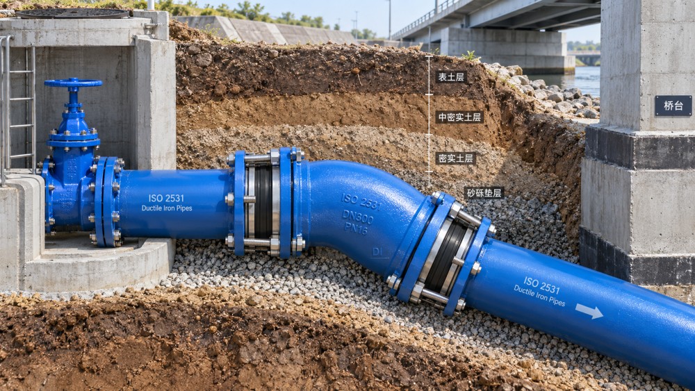
A socketed elbow, tee, flange adaptor, coupling, or special fitting may be supplied under an ISO 2531-related specification while using different joint arrangements at each end. One end may be push-in, another restrained, and another flanged. Each interface should be reviewed separately. A flexible push-in connection should not automatically be treated as an anchored connection. A restrained joint should not automatically be treated as a joint that can tolerate large angular rotation. Flanged connections are generally more rigid and may require particular attention where a flexible buried run connects to a chamber-mounted valve or pump assembly.
Quality documentation should clearly distinguish between the compliance evidence for the ductile iron fitting and the performance evidence for the joint. Useful records include approved drawings, declared allowable deflection, pressure test information relevant to the joint configuration, gasket material identification, restraint component specifications, assembly instructions, and compatibility confirmation for the pipe outside diameter and joint range.
Verify pressure capability at the actual operating condition
Pipeline movement and pressure do not act independently. Internal pressure tends to separate joints, creates thrust at changes in direction, and can increase the consequences of small installation errors. A fitting selected only against nominal pressure may be adequate for static service but insufficient when transient pressure, surge events, or seismic movement are considered together.
The review should compare the fitting, joint, gasket, and restraint ratings with the full pressure envelope: normal operating pressure, temporary pressure, test pressure, and anticipated transient conditions where the project design includes them. The limiting component may not be the ductile iron body. It may be the gasket, gland, bolt set, locking device, or the allowable joint deflection under pressure.
A common review error is to accept one general pressure value printed on a data sheet without confirming whether it applies to an unrestrained joint, a restrained joint, the maximum deflection position, or a straight pipe connection. The acceptance record should state the exact assembly being approved, not just the material class of the fitting.
Restraint must match the load path
Seismic flexibility is valuable only when the pipeline has a controlled load path. At bends, tees, reducers, valves, dead ends, and changes in elevation, pressure thrust and ground-induced loads must be transferred through restraint, anchorage, soil resistance, thrust blocks, or a designed combination of these measures. A fitting can be technically sound while the system around it remains vulnerable to separation.
Unrestrained push-in joints can accommodate limited rotation and simplify installation, but they do not resist axial pull-out unless the system design provides restraint elsewhere. Restrained joints can resist longitudinal force, yet their locking mechanism, gland bolts, weld beads, or gripping elements must be installed exactly as intended. Missing components, incorrect torque, incompatible pipe surface conditions, or an incorrect insertion depth can reduce restraint performance.
Pay particular attention to transitions between buried and rigid sections. Pipe entering a concrete chamber, crossing a wall, connecting to a valve assembly, or emerging above ground may be subjected to concentrated movement. The flexible section needs sufficient developed length and appropriate joint placement to distribute deformation. Placing one “flexible” fitting immediately against a rigid wall does not automatically create seismic isolation.
Questions that should be resolved before release for installation
- Is the connection intended to rotate, translate axially, resist pull-out, or perform more than one of these functions?
- Where will pressure thrust be resisted after movement occurs?
- Does the design rely on soil restraint, concrete thrust blocks, restrained joints, anchors, or a combination?
- Are flexible joints located where movement is expected, rather than simply wherever they are convenient to install?
- Does the fitting orientation leave room for socket insertion, bolt access, coating repair, and future inspection?
Inspect the gasket and coating as functional components
In a seismic application, the gasket is not a minor accessory. It must seal under compression while tolerating the joint’s permitted angular position and pressure condition. Check that the gasket type matches the specified joint, diameter, fluid service, and any project requirements for elastomer material. A gasket that is dimensionally close but not approved for the socket profile can roll, twist, pinch, or seat unevenly during assembly.
Field inspection should confirm that gasket grooves are clean, the gasket is correctly positioned, lubricant is compatible with the joint system, and pipe ends are properly prepared. Dirt, excess coating build-up, damaged spigot ends, or poorly controlled insertion can create a leak path that may not appear until pressure cycling or movement occurs. Marking the insertion depth on the pipe before assembly helps identify over-insertion or insufficient engagement.
Coating condition deserves equal attention. Buried ductile iron fittings may carry external coatings selected for the expected soil environment and internal linings selected for the conveyed water. Handling damage near sockets, bolt holes, lifting points, or sharp changes in fitting geometry can expose metal at locations that are difficult to repair after backfilling. Where repair is permitted, use the specified repair material and document the affected area. Do not apply an unapproved field coating that interferes with gasket seating, restraint engagement, or dimensional fit.
Traceability should remain attached to the installed component
Material traceability is often lost between delivery and burial. For safety-critical pipeline sections, receiving inspection should link each fitting or lot to its identification markings, certificates, coating or lining records where provided, joint accessories, and installation location. This is especially important where visually similar fittings have different pressure classes, joint types, or restraint arrangements.
Check that product marking remains legible and corresponds with the approved submittal: nominal size, relevant standard designation, pressure or class information where marked, manufacturer identification, and production traceability reference as applicable. A certificate alone is not enough if it cannot be tied to the physical fitting. Conversely, markings alone do not demonstrate that the delivered fitting has the required joint accessories or seismic-use configuration.
Receiving personnel should also inspect for shipping damage that can affect function: distorted sockets, chipped cement lining, cracks in coatings, missing glands, mixed gasket types, incomplete restraint kits, damaged threads, or bolts substituted without approval. Segregate nonconforming components before they reach the trench; corrective work becomes harder once fitting ends and accessory kits are mixed across installation areas.
Installation controls often decide whether the design intent is preserved
Even a well-selected ISO 2531 fitting assembly can fail to provide the intended movement capacity if trench preparation and joint assembly are poorly controlled. Bedding must support the fitting without introducing point loads under bells, glands, or branches. Large stones, hard contact points, voids, and uneven compaction can concentrate stress at the socket or prevent the pipeline from moving as designed.
Alignment should be set before final joint completion. Do not force a pipe into a socket at the maximum allowed angle merely to correct a route error. The allowable deflection is an operating limit, not a substitute for poor layout. Keep movement reserve where the design requires it, especially in areas subject to settlement or seismic displacement.
For restrained assemblies, verify the tightening sequence, specified torque method, bolt condition, and uniform engagement of locking components. Where the fitting uses mechanical couplings or glands, inspect the gap and position around the circumference rather than relying on one visible point. After backfilling begins, protect the fitting from impact and prevent large rocks from bearing against joints or restraint hardware.
When a seismic claim needs further engineering confirmation
Additional review is warranted when the pipeline crosses an identified fault zone, connects structures expected to move independently, operates at high consequence locations, passes through liquefaction-prone ground, or uses a nonstandard combination of fittings and joint systems. The design team may need to evaluate imposed displacement, longitudinal strain, thrust transfer, support stiffness, and the number of joints available to absorb movement. Product documentation cannot replace that system-level assessment.
The practical acceptance decision should be based on a complete chain of evidence: the fitting conforms to the specified standard and class; the joint type has declared movement and pressure limits; restraint is designed for the expected load path; gaskets and accessories are compatible and traceable; coatings and linings remain intact; and the field installation preserves the intended geometry. When any link is missing, describing the assembly as seismic flexible creates more confidence than the documented evidence supports.
Related News
- Using Industrial Air Blow Guns to Clear Chips Without Spreading DebrisOct 15, 2026Fluid Power Control Strategist
- Ductile Iron Pipe Valves: Which AWWA Standards Apply to Water Main Projects?Oct 15, 2026Dr. Elias Vance
- Why Vacuum Suction Cups Lose Grip on MDF in Woodworking MachinesOct 15, 2026CNC Kinematics Architect
- Choosing a Variable Displacement Piston Pump Manufacturer: What to VerifyOct 15, 2026Fluid Power Control Strategist
- Parallel vs. Angular Pneumatic Grippers for Confined Assembly StationsOct 15, 2026Fluid Power Control Strategist
- Die Castings vs. Investment Castings: Which Costs Less at Your Production Volume?Oct 14, 2026Foundry Phase-Change Fellow