
How to Specify Seismic Flexible DI Fittings for Required Angular Deflection
Start with the movement demand at the fitting location, then select a ductile iron jointed fitting whose published angular deflection, pressure capability, restraint arrangement, and pipe-end geometry remain valid under that demand. A nominal diameter and pressure class alone do not establish seismic suitability. The fitting must accommodate the expected relative rotation between adjoining pipe barrels without exceeding the joint's tested range, losing gasket compression, imposing excessive bending on connected components, or transferring unaccounted thrust into the pipeline.
For seismic flexible ductile iron fittings with angular deflection, the central specification question is: what rotation must each joint accept after the pipeline, soil, supports, and connected structures move relative to one another? That question should be answered at each movement-sensitive location, especially near fault crossings, bridge approaches, buried-to-exposed transitions, valve chambers, pump stations, building penetrations, and connections between different pipe materials.
Define the Required Deflection Before Selecting the Fitting
Angular deflection is the change in alignment between two connected pipe or fitting spigots. It is often expressed as degrees per joint, although some submittals describe it through allowable lateral offset over a stated pipe length. These descriptions are related but are not interchangeable unless the effective joint-to-joint length is known.
A pipeline can require angular movement for several reasons at once. Seismic ground displacement can rotate adjacent buried segments. Differential settlement can create a gradual change in grade. Thermal movement in exposed pipe can affect branch connections. Construction tolerances can leave an installed run slightly out of line before any seismic event occurs. The specified angular capacity must cover the combined installed condition and the design movement, with an appropriate project-defined allowance rather than assuming the full published joint angle is available for one source of movement.
A useful evaluation begins by separating three quantities:
- Initial installation deflection: rotation already used to follow the trench line, correct minor alignment error, or connect pipe laid on a curve.
- Operational movement: rotation associated with settlement, temperature change, pressure cycles, vibration, or normal structural movement.
- Seismic movement demand: the rotation expected during the governing ground-motion or displacement condition, including differential movement at interfaces.
These values should not be added blindly. Their direction, timing, and load combination must follow the project design basis. Still, treating the installed deflection as zero without field evidence is a frequent source of overstatement. A joint installed near its permitted angle has little remaining capacity for a later event.
Read Catalog Deflection Values Carefully
A published deflection rating often applies to a specific joint configuration, diameter range, gasket type, insertion depth, and pressure condition. It may describe the capability of one socket-and-spigot joint rather than the total turn available through a fabricated bend. A flexible fitting with several joints can distribute a change in direction, but only when its layout allows each joint to share movement as intended.
Do not assume that a fitting marked as flexible will rotate freely in every plane. Some arrangements are designed primarily for limited field adjustment; others are intended to provide a defined movement range under pressure. A restrained joint may have a different allowable deflection from its unrestrained version because locking segments, weld beads, gripping elements, or restraint glands affect the rotation envelope. The applicable value is the value for the complete assembled joint, not the value of a comparable nonrestrained coupling.
Manufacturer documentation should clearly identify whether the stated angle is:
- the maximum per joint under the stated test condition;
- the permitted angle for installation only;
- a value reduced when the joint is pressurized or restrained;
- an angle measured from a centered position, rather than a total range across both directions; or
- an assembly value that assumes full spigot insertion and no adverse field gap.
Field deflection beyond the recommended installation limit can produce a misleading result: the line may pass a short-duration hydrostatic test while the gasket is seated unevenly, the spigot bears on one side of the socket, or the restraint hardware is no longer loaded symmetrically. Such a joint has less tolerance for pressure surge and future displacement.
Translate Pipeline Geometry Into Joint Rotation
The geometry of the connection determines whether an angular-deflection fitting is the appropriate device. A small change in pipe direction over a long distance may be accommodated by distributing deflection over several standard joints, provided that each joint stays within its approved range and the route does not cross a concentrated displacement zone. A sharp relative movement over a short length calls for a purpose-designed flexible assembly, expansion joint arrangement, or a redesigned transition.
For small angles, the lateral offset associated with a joint rotation is approximately related to pipe segment length and the sine of the rotation angle. This relationship explains why a deflection value cannot be evaluated without pipe length. The same angle produces a much greater offset across a long pipe barrel than across a compact fitting spool. Conversely, a specified offset at a valve vault wall may demand a relatively large rotation if the available flexible length is short.
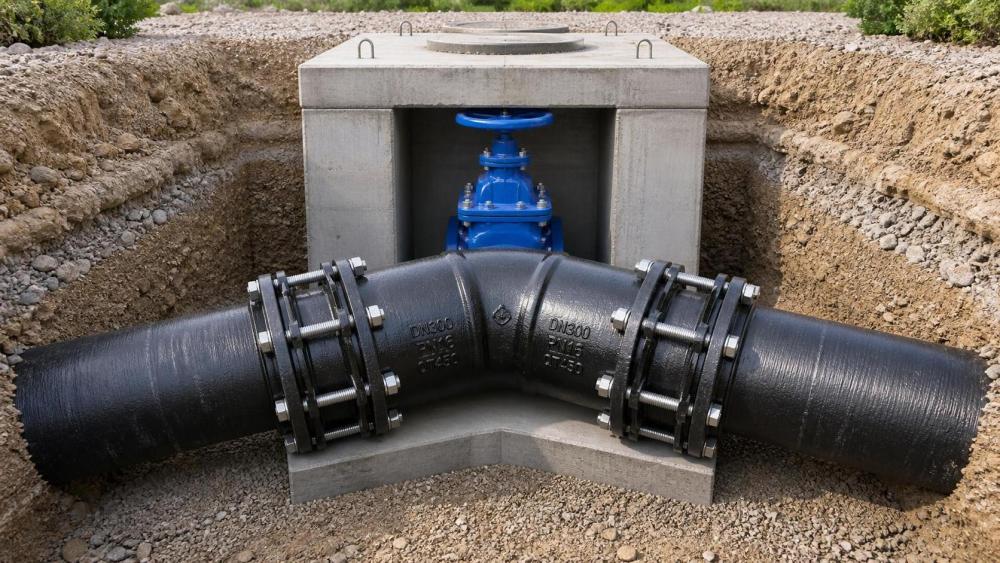
Model the actual centerline geometry, including the fitting face-to-face dimensions, restrained lengths, valve body lengths, flange adapters, and wall penetrations. Simplified drawings that treat every connection as a point can conceal the concentration of movement at the first joint outside a rigid structure. That first joint is often the limiting location because the structure moves differently from the buried pipeline.
Use Multiple Joints as a System, Not as a Nominal Total
A fabricated flexible bend or offset section may include two or more joints. It is tempting to multiply the catalog angle by the number of joints and call that the available deflection. Equal sharing only occurs under favorable geometry and support conditions. A short spool can behave differently from a long spool; one joint may rotate first because of trench restraint, local soil stiffness, pipe weight, or a nearby valve restraint. The assembly drawing should show the intended neutral position, permitted rotation at each joint, spool lengths, and any required support or guide locations.
Where the predicted movement is directional, orient the assembly so that its useful movement plane aligns with the expected displacement. A fitting intended to flex laterally offers limited benefit if the controlling movement is axial pull, vertical settlement, or torsion around the pipe axis. Compound movement sometimes requires separate mechanisms: a restrained flexible joint for rotation, an expansion provision for axial movement, and a designed support arrangement for vertical load.
Restraint Changes the Selection
Pressure thrust at bends, tees, reducers, dead ends, valves, and changes in section must be resolved by thrust blocks, restrained joints, anchors, or a combination defined by the pipeline design. Seismic flexibility does not eliminate thrust. In fact, a flexible connection placed near a directional fitting can change how loads are transmitted into adjacent pipe and restraint lengths.
An unrestrained push-on joint may permit angular deflection but can separate under pressure thrust if the surrounding system does not provide sufficient restraint. A fully restrained configuration prevents pullout, yet its restraint mechanism must remain functional through the specified angle and movement cycle. The product submittal should state the allowable deflection for the restrained assembly, the compatible pipe outside diameter range, coating limitations at gripping surfaces where relevant, and the conditions under which restraint ratings apply.
Rigid anchorage on both sides of a flexible fitting can also defeat its purpose. If an assembly is expected to accommodate differential movement, the adjacent pipeline lengths need sufficient freedom to rotate into the assembly. Excessively short restrained segments, concrete encasement, tightly compacted zones, or improperly located guides can force bending into a pipe barrel, flange, valve neck, or fitting body instead.
Specify the Complete Joint Envelope
The fitting schedule should state more than size, nominal pressure class, and fitting angle. It should identify the required angular deflection at each joint or assembly, the installation angle, the movement plane, the anticipated axial displacement if any, and whether the joint must be restrained. Where movement is cyclic or repeated, request confirmation that the proposed joint is suitable for the stated service rather than assuming that a one-time deflection test represents fatigue performance.
Pressure must be evaluated at the joint's maximum required deflection, not only in a straight, centered condition. Include normal operating pressure, surge allowance where applicable, test pressure, and any vacuum or negative-pressure condition that could affect gasket stability. Internal pressure loads the gasket differently from external soil or structural loads, so the governing condition may not be the highest pressure alone.
Ductile iron fitting material, wall thickness, casting quality, and coating system remain relevant even when flexibility is supplied by the joint. Confirm that the fitting body is suitable for the service pressure and burial environment, and that the lining and external coating match the connected pipe system. Cementitious linings, epoxy systems, zinc-rich external layers, polyurethane coatings, and repair materials have different field-handling limits. The joint detail must preserve corrosion protection after installation; a protective coating damaged by restraint hardware, aggressive backfill, or poor field repair can create a localized durability problem around an otherwise sound connection.
Standards, Drawings, and Submittal Evidence
Reference the waterworks, utility, or project standards that govern the pipe and joint system, then require the proposed fitting to demonstrate compatibility with those requirements. A standard applicable to ductile iron fittings does not automatically verify the seismic displacement performance of a particular flexible assembly. The submittal needs to bridge that gap with product drawings, joint details, pressure and deflection limitations, restraint information, installation instructions, and material or coating documentation appropriate to the project.
Dimensions deserve close attention. Pipe outside diameter tolerances, socket dimensions, spigot geometry, wall thickness, flange drilling, and actual face-to-face lengths must match the connected system. This is particularly important at transitions between ductile iron pipe and steel, PVC, HDPE, or fabricated spool pieces. A coupling or adapter may fit the nominal size while still being unsuitable for the outside diameter, end condition, or restraint method in the field.
Request an assembly drawing for any nonstandard seismic detail. It should show each component in order, insertion marks, gasket locations, restraint components, allowable angular positions, spool lengths, and clearances for bolt tightening or access. A general catalog image is not sufficient evidence that the exact assembly will fit between a wall, valve, or existing flanges.
Installation Details That Preserve Deflection Capacity
Flexible joints are vulnerable to preventable installation errors. Pipe ends must be clean, undamaged, and compatible with the specified gasket and restraint arrangement. Proper lubrication, insertion depth, and gasket seating matter because angular movement is developed from a correctly centered starting position. A joint assembled with an excessive insertion gap, skewed gland, or damaged coating may appear aligned at rest but lose sealing margin under pressure or movement.
Install the assembly near its intended neutral position unless the design specifically allocates a biased starting angle. A neutral position leaves movement available in both directions. Where the alignment must begin off-center, the drawings should state the installed angle and show that the remaining range covers the governing displacement direction.
Backfill and support conditions need the same level of attention as the fitting. Large rock directly against the socket, voids beneath a pipe, abrupt changes in embedment, or uncontrolled compaction near a flexible section can concentrate rotation at one joint. Around above-ground assemblies, supports should carry pipe weight without clamping the intended rotation point. Nearby valves and flanged equipment require independent support so their mass does not become an unintended bending load on the flexible fitting.
Before pressure testing, verify actual joint angles and record insertion marks where the joint design uses them. After test completion and before final cover, inspect accessible restraint elements, gasket areas, coatings, and the installed assembly orientation. These records are especially valuable where a later surface inspection cannot confirm whether the fitting retained its specified movement position.
A sound specification defines the required movement first, assigns that movement to real joints and real geometry, and then verifies pressure, restraint, installation, and corrosion details as one connected condition. Treating angular deflection as an isolated catalog number leaves the most consequential questions unanswered.
Related News
- How to Assess a Rigid Coupling Supplier for Bore Accuracy and Traceable QualityOct 08, 2026Tribology & Kinematics Expert
- Titanium Alloys Compared: Balancing Strength, Corrosion Resistance, and MachinabilityOct 08, 2026CNC Kinematics Architect
- Where Ductile Iron Dismantling Joints Reduce Alignment Risk in Water PipelinesOct 08, 2026Pipeline Metallurgy Scientist
- Selecting a Precision Bearing Sleeve: Fits, Runout, and Material ChoicesOct 08, 2026Tribology & Kinematics Expert
- Face Milling Cutters: How Insert Geometry Affects Finish on Steel and AluminumOct 08, 2026CNC Kinematics Architect
- Single-Acting Cylinders for Clamping: Stroke, Force, and Return Spring ConsiderationsOct 07, 2026Fluid Power Control Strategist