
How Ductile Iron Expansion Joints Handle Seismic Movement and Pipeline Misalignment
When a buried pipeline crosses a fault zone, passes through mixed soil conditions, or is tied into older sections that were never perfectly aligned, the question is rarely whether movement will happen. The real question is how much movement the system can absorb before joints leak, bolts overstress, or connected equipment starts taking loads it was never meant to see. That is why Ductile Iron Expansion Joints matter so much in modern water, utility, and industrial piping design. They are not just accessories added at the end of a drawing package. In many projects, they are the engineered buffer between normal system movement and avoidable failure.
For project managers and engineering leads, this topic usually comes up at a practical moment: a consultant flags seismic design requirements, an installation team reports field misalignment, or a rehabilitation project reveals that as-built conditions do not match the drawings. At that point, understanding how expansion joints behave under seismic movement and pipeline misalignment becomes essential for risk control, installation planning, and long-term asset reliability.
Why movement in piping systems is more complicated than it looks
Pipeline movement is often discussed as if it were a single issue, but in the field it usually comes from several sources acting together. Temperature change causes axial expansion and contraction. Settlement can create vertical displacement over time. Traffic loading, vibration, pump startup, and transient pressure events add repeated stress cycles. In seismic regions, the system may face sudden lateral offset, angular deflection, or extension and compression far beyond normal operating movement.
Misalignment has its own causes. It may come from trench conditions, uneven supports, tie-in work during retrofits, fabrication tolerances, or the reality that long pipe runs rarely remain perfectly straight once installed. What seems like a minor offset at one point can translate into concentrated stress at flanges, valves, and rigid couplings somewhere else in the line.
A rigid connection will try to force the pipeline back into position. An expansion joint, by contrast, is intended to accept controlled movement while maintaining pressure integrity. In ductile iron systems, that distinction is especially important because the piping network often serves public water, wastewater, fire protection, or industrial process duty where leakage and service interruption carry broader operational consequences.
How Ductile Iron Expansion Joints actually work
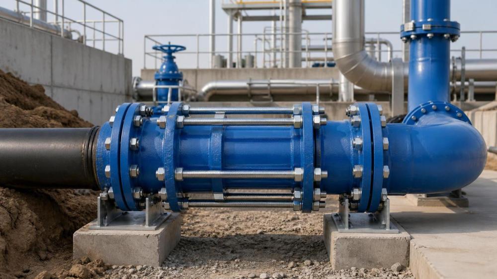
Ductile Iron Expansion Joints are designed to accommodate axial movement, limited lateral displacement, and angular deflection within a defined range. The joint body provides structural strength, while sealing elements and internal geometry allow the assembly to move without losing containment. Depending on design, the joint may be restrained or unrestrained, and may include telescoping sections, follower glands, tie rods, limit rods, or flexible sealing systems that maintain compression as the joint shifts.
The use of ductile iron in the body is significant. Compared with more brittle iron materials, ductile iron offers better toughness, tensile performance, and impact resistance. That makes it a strong fit for buried infrastructure and municipal networks where external loading, handling conditions, and long service life all matter. The expansion capability does not come from the metal stretching like rubber; it comes from the engineered geometry of the joint assembly and the controlled travel built into it.
From a project perspective, the most useful way to think about these joints is not as “movement absorbers” in a vague sense, but as components that redistribute strain. Instead of allowing thermal, seismic, or alignment stress to concentrate at one weak location, they create a managed zone where the system is expected to move.
Seismic movement: what the joint is expected to survive
Seismic design is not only about a catastrophic earthquake scenario. It is also about preserving system function when the ground shifts faster and less predictably than normal civil movement assumptions allow. During a seismic event, pipelines may experience axial pull, compression, rotation, and offset at the same time. Buried sections can move with the soil, while above-ground or anchored sections respond differently, creating differential movement at transitions.
In these conditions, Ductile Iron Expansion Joints help by introducing flexibility where rigid flanged or straight mechanical connections would otherwise pass movement directly into the pipeline, valve bodies, pumps, or wall penetrations. A properly selected joint can accommodate a portion of this relative displacement, reducing the chance of cracked fittings, pulled bolts, leaking seals, or damaged supports.
That said, no expansion joint should be treated as a universal seismic cure. Its performance depends on movement range, restraint strategy, pressure rating, support layout, and installation location. In practice, seismic success often comes from the system approach: flexible joints at strategic points, suitable anchoring, clear load paths, and enough design coordination to avoid turning one movement problem into another.
Where they are most often used in seismic-sensitive layouts
Project teams commonly evaluate expansion joints near building entries, at pump stations, around tanks and treatment facilities, at bridge crossings, and at connections between new and existing pipe sections. These are the places where differential movement is most likely to occur. A buried main may move with surrounding soil, while a concrete structure or equipment pad moves differently. The joint acts as a transition element between those behaviors.
For municipal and utility applications, that function is particularly valuable because the pipeline is expected to keep serving under difficult conditions. Water loss, contamination risk, or outage after a seismic event can turn a mechanical issue into a public service issue very quickly.
Handling pipeline misalignment without forcing the system
One of the most common field uses for Ductile Iron Expansion Joints is not dramatic seismic displacement but ordinary installation misalignment. This is where the component often delivers immediate value. In rehabilitation work, contractors frequently discover that legacy piping has small offsets, non-standard dimensions, or settlement-induced deflection that was never fully documented. Trying to “pull” pipe into line with bolting force may appear to solve the problem during installation, but it builds hidden stress into the system from day one.
An expansion joint can absorb that mismatch more safely within its allowable movement envelope. Instead of using adjacent valves, flanges, or fabricated spool pieces as correction tools, the joint provides a designated adjustment zone. This reduces the chance of warped flange faces, uneven gasket compression, or premature leakage.
Still, there is an important limit here. Expansion joints are not a substitute for poor layout control. If the field error exceeds the joint’s rated axial, lateral, or angular capacity, the system is simply transferring the problem into a component not designed to carry it. Good practice means measuring the actual offset, comparing it with the manufacturer’s movement limits, and confirming how the joint will behave once the line is pressurized and restrained.
Selection criteria that matter more than many buyers expect
For project managers, the challenge is often not finding an expansion joint in a catalog. It is making sure the selected joint fits the actual movement case and installation environment. Several evaluation points deserve close attention.
Movement type and magnitude
Axial travel is only one part of the picture. A project may involve angular deflection at a structure connection, lateral shift from settlement, or combined movements during seismic loading. The joint must be assessed against the real movement profile, not just a single advertised expansion value.
Pressure and thrust loads
Internal pressure can create thrust forces that act on the joint and surrounding system. If the design is unrestrained, anchors and supports must be capable of carrying those loads. If restraint hardware is used, the load path changes and should be checked carefully. This point is often underestimated during fast-track projects.
Material and corrosion environment
Ductile iron body performance is closely tied to coating systems, external corrosion exposure, internal water quality, and installation conditions. In buried service, soil chemistry, moisture, and stray current risk can influence long-term durability. Protective linings and coatings are part of the joint specification, not decorative extras.
Connection compatibility
Flange drilling, face dimensions, pipe standards, and adjoining component tolerances need to match. In mixed-material systems or retrofit jobs, connection details can become the hidden source of schedule delays.
Maintenance access
Even in buried systems, some joints are placed in chambers, plant rooms, or vaults where inspection is possible. In those locations, accessibility for bolt checking, leak observation, and future replacement can shape the best product choice.
Standards, submittals, and the documentation side of decision-making
Searches around this topic often come from teams looking for technical and standard-related guidance, not just product descriptions. That makes documentation critical. Expansion joints for ductile iron piping should be reviewed in the context of applicable pipe standards, flange standards, pressure class requirements, municipal specifications, and where relevant, seismic or building code expectations for the installation zone.
Project teams should ask for clear submittal information on movement capacity, pressure rating, materials, coatings or linings, bolt requirements, dimensional tolerances, and installation instructions. If the joint is intended for a seismic function, that intent should be explicit in the design review rather than assumed from general flexibility language.
For procurement and EPC teams, this is where platforms such as IMPE can be useful: not by replacing engineering approval, but by organizing the technical categories that often get scattered across supplier literature. When teams compare ductile iron piping components, fittings, and joint systems, structured information helps separate nominal compatibility from true application fit.
Installation realities that influence whether the joint performs as designed
Many joint problems begin after the right product has already been selected. Overextension during installation, poor alignment at assembly, uneven bolt tightening, missing restraint details, or unsupported pipe weight can all compromise performance. In buried applications, backfill quality and trench geometry also matter because they influence how movement is transmitted into the pipeline.
It is worth remembering that an expansion joint is a moving component placed inside a system that often wants to behave rigidly. If supports, anchors, and surrounding pipe runs are not coordinated with that movement, the joint may not move where or how the design intended. Instead, the line can bind, twist, or impose side loads on the sealing surfaces.
For project managers, this translates into a simple but important lesson: review installation assumptions early. The best time to discover that a vault has no room for joint travel or that adjacent supports block deflection is before procurement, not during commissioning.
Common misunderstandings in project planning
One recurring misconception is that any flexible-looking component automatically provides seismic protection. Another is that expansion joints can correct major field errors without engineering review. Both assumptions create risk.
There is also a tendency to focus only on initial fit-up. A joint that installs easily may still perform poorly if thermal cycles, pressure thrust, and soil movement were not considered together. Conversely, a joint that appears more complex on paper may be the more reliable choice once the full lifecycle of the pipeline is considered.
The most successful projects usually treat Ductile Iron Expansion Joints as part of a system conversation involving pipe material, fittings, valves, anchorage, trench conditions, and operational loads. That broader view is especially important in municipal infrastructure, where pipelines are expected to remain serviceable for decades under conditions that change long after construction crews have left the site.
What project leaders should confirm before approval
Before approving an expansion joint for seismic movement or pipeline misalignment, ask a few grounded questions. What exact movement is expected, and where will it occur? Is the joint rated for that movement in the installed configuration? How will pressure thrust be restrained? Are coatings and lining systems suitable for the service environment? Do the connection details match the actual pipe and flange standards on site? Can the installation team place the joint without forcing it out of its neutral position?
These are not abstract engineering questions. They are schedule, reliability, and risk questions. A well-chosen joint can preserve flexibility, reduce stress concentration, and improve resilience at critical connection points. A poorly matched one may simply delay failure until the system is pressurized or the ground eventually moves.
In that sense, Ductile Iron Expansion Joints earn their value quietly. They do not usually define a project in the way pumps, valves, or major pipeline lengths do. But when seismic movement, settlement, thermal change, or real-world misalignment shows up, they often become the component that keeps the rest of the system from paying the price.
Related News
- How to Assess a Rigid Coupling Supplier for Bore Accuracy and Traceable QualityOct 08, 2026Tribology & Kinematics Expert
- Titanium Alloys Compared: Balancing Strength, Corrosion Resistance, and MachinabilityOct 08, 2026CNC Kinematics Architect
- Where Ductile Iron Dismantling Joints Reduce Alignment Risk in Water PipelinesOct 08, 2026Pipeline Metallurgy Scientist
- Selecting a Precision Bearing Sleeve: Fits, Runout, and Material ChoicesOct 08, 2026Tribology & Kinematics Expert
- Face Milling Cutters: How Insert Geometry Affects Finish on Steel and AluminumOct 08, 2026CNC Kinematics Architect
- Single-Acting Cylinders for Clamping: Stroke, Force, and Return Spring ConsiderationsOct 07, 2026Fluid Power Control Strategist