
Flexible Pipe Joint Selection for Seismic Movement and Pipeline Misalignment
A flexible pipe joint is not selected by asking whether a pipeline needs “some movement.” The critical question is what movement will occur at a specific location, in which directions, under what pressure condition, and with what restraint arrangement. A joint that accommodates a small installation offset may be unsuitable for differential settlement; a joint that performs well under thermal cycling may not provide the travel needed across a seismic separation. In pressurized networks, an incorrect choice can transfer unintended loads into valves, pumps, wall penetrations, thrust blocks, and adjacent pipe barrels.
For seismic movement and pipeline misalignment, the selection process must begin with the movement envelope rather than the product catalogue. The joint must accommodate the predicted displacement without exceeding its published limits, while the pipeline system must remain stable if the joint extends, compresses, rotates, or loses support. Flexibility and restraint are related but different design functions. Treating them as interchangeable is one of the most consequential errors in pipeline projects.
Define the movement before selecting the joint type
Pipeline movement is rarely purely axial. A buried water main crossing a fault zone, a pipe rack connected between independent structures, and a process line passing through a building wall can all experience different combinations of axial, lateral, angular, and rotational displacement.
- Axial movement is extension or compression along the pipe centerline. It may result from temperature change, settlement, structural drift, or seismic separation.
- Lateral movement shifts one pipe end sideways relative to the other. This is common where a pipeline bridges an expansion joint, crosses between structures, or encounters differential ground movement.
- Angular deflection occurs when connected pipe sections rotate relative to each other. It is often associated with minor alignment deviations, gradual settlement, or movement at a pipe support.
- Rotation or torsion is less frequently considered but can be important in vertical risers, mechanically coupled assemblies, and connections near equipment subject to vibration.
These movements should be defined as a combined design case, not evaluated one at a time. A flexible pipe joint may have an allowable angular deflection and a separate axial travel value, but its usable capability can be reduced when both occur simultaneously. Manufacturers’ movement ratings must therefore be interpreted as a system of limits, not as independent values that can all be used at their maximum level.
Installation misalignment must also be separated from service movement. If a coupling is installed at the edge of its allowable angular or lateral range merely to close a construction gap, little movement capacity remains for settlement, thermal growth, vibration, or seismic displacement. The installed position should normally leave sufficient reserve travel in the expected operating direction.
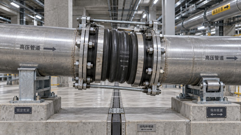
Different flexible joints solve different problems
The phrase flexible pipe joint covers several product categories with substantially different operating principles. Selection should be based on the movement mechanism, pipe material, pressure class, environmental exposure, and the way axial force is controlled.
Mechanical flexible couplings
Bolted sleeve-type couplings with elastomeric gaskets are widely used to connect plain-end pipe, repair cut sections, and accommodate limited angular deflection or installation tolerance. Depending on their design and approval, they may be used on steel, ductile iron, cast iron, PVC, HDPE, or other pipe materials. However, compatibility cannot be assumed from nominal diameter alone. Outside diameter, end geometry, coating thickness, pipe ovality, and wall stiffness all affect gasket sealing and grip performance.
These couplings are particularly useful where field-cut pipe ends make conventional spigot-and-socket connections impractical. Their flexibility is generally intended for modest deflection and alignment adjustment rather than large seismic offsets. A standard mechanical coupling should not automatically be treated as a seismic expansion device.
Restrained couplings and expansion couplings
Where pressure thrust must be transferred across the joint, a restrained coupling or purpose-designed restrained expansion assembly may be required. Restraint systems can use grip rings, wedges, lugs, tie rods, harnesses, or other mechanisms, depending on pipe material and joint design. The restraint capacity must be evaluated for the actual pipe outside diameter, wall thickness, coating condition, and pressure thrust.
Some expansion couplings provide controlled axial travel while maintaining a sealed pressure boundary. They can be appropriate where thermal movement, structural separation, or settlement acts substantially along the pipe axis. Their application depends heavily on guides, anchors, and stops. Without correct support design, the joint may absorb movement it was not intended to take, or the entire line may migrate toward the available travel.
Rubber expansion joints
Rubber expansion joints can absorb vibration and accommodate axial, lateral, and angular movement within defined limits. They are common near pumps, fans, treatment equipment, and industrial process connections. Their flexibility comes from the elastomer body and reinforcement layers rather than from sliding metal components.
They should not be selected solely because they appear capable of large movement. Internal pressure produces axial thrust, which can be substantial at larger diameters. Control units, tie rods, anchors, or independently restrained pipe may be needed to prevent overextension. Material selection also matters: elastomer compatibility must be checked against the conveyed fluid, temperature, disinfectants, oils, chemicals, and external ozone or ultraviolet exposure.
Metal bellows expansion joints
Metal bellows joints are generally used in engineered industrial piping where temperature cycling, high temperature, vacuum, or process-fluid compatibility makes elastomeric options unsuitable. They can be designed for axial, lateral, angular, or universal movement, but they demand disciplined piping design. Bellows are not tolerant of uncontrolled misalignment, torsion, inadequate guides, or unrestrained pressure thrust.
A bellows assembly that is correct on a piping stress calculation can fail prematurely if installed with unaccounted pipe offset, damaged during handling, or exposed to cyclic displacement outside its design range. For seismic applications, the required cycle life and transient displacement assumptions must be explicitly addressed rather than inferred from a general thermal-expansion specification.
Ball joints, swivel joints, and articulated assemblies
Where large angular movement is expected, particularly in complex industrial routing or multi-directional displacement zones, ball joints or articulated assemblies may be more appropriate than a single expansion joint. These arrangements can redirect movement through geometry, but they require space, support planning, and careful consideration of pressure thrust and load transfer. They are not simple replacements for a flexible coupling at a wall penetration.
Seismic performance depends on the pipeline system, not the joint alone
A joint may be described as flexible, but that does not establish that the pipeline will perform acceptably during seismic movement. Seismic design must consider the relationship between the pipe, soil, supports, structures, equipment, and the joint’s movement capacity.
For buried pipelines, the controlling issue may be permanent ground deformation, liquefaction-related settlement, fault displacement, soil strain, or differential movement at connections to rigid structures. A joint located immediately beside a valve chamber or building entry may see greater distortion than a similar joint in uniform trench conditions. Flexible joints can localize movement, but excessive concentration of strain at one connection can simply move the failure risk to the adjacent pipe or fitting.
For above-ground piping, the concerns are different. Structural drift between floors or buildings, movement across seismic separation joints, support sway, equipment displacement, and anchor loads become central. The pipe must be guided so that motion enters the flexible assembly in the direction for which it was designed. A lateral expansion joint cannot provide its intended travel if nearby supports bind the pipe, and a rubber connector at a pump cannot compensate for building drift across a structural joint unless it has been specifically sized and restrained for that displacement.
Pressure thrust must be calculated wherever an unrestrained pressurized joint can extend. The basic force is related to internal pressure and effective area. Larger diameter systems can develop very high axial forces even at moderate operating pressure. This force does not disappear because a joint is flexible; it must be resisted by anchors, restraint devices, thrust blocks, structural connections, or a joint design that contains the thrust internally.
Seismic movement can also occur while the line is pressurized. The joint therefore needs adequate capacity under the relevant pressure condition, not merely during an unpressurized installation check. Surge pressure, transient events, vacuum conditions, and pressure-test requirements should be included where applicable.
Misalignment is a construction condition, not a reason to relax tolerances
Field alignment problems commonly arise at tie-ins, repair sections, valve replacements, transitions between pipe materials, and connections to fabricated spools. A flexible coupling can be valuable because it reduces the need for forcing pipe ends into line. Yet it should not become a substitute for correcting poor route control, incorrect spool dimensions, uneven supports, or damaged pipe ends.
Before approving a joint for misalignment, establish whether the observed offset is angular, lateral, axial, or a combination. An angular deviation can sometimes be accommodated by a coupling over a short pipe length, but the same visual offset across a very short gap may represent excessive angular deflection. A lateral offset may require a purpose-designed offset spool, multiple joints, or a longer flexible assembly rather than a single coupling installed under side load.
Pipe end condition deserves equal attention. Gaskets seal against surfaces, not nominal specifications. Corrosion pitting, weld beads, out-of-round ends, thick coating transitions, gouges, and inadequate insertion depth can compromise a connection that appears correctly bolted. For ductile iron and steel systems, the specified joint arrangement must also align with the applicable pipe and fitting standards. In waterworks applications, project specifications may refer to standards such as AWWA C111 for rubber-gasket joints and AWWA C219 for bolted sleeve-type couplings; the relevant edition and project jurisdiction should govern rather than a generic reference in a supplier submittal.
Material compatibility is part of movement reliability
Joint flexibility is of little value if corrosion, gasket degradation, or coating damage shortens the service life of the connection. The material review should include the pipe, coupling body, fasteners, gaskets, internal wetted components, and external protection system.
For potable and raw water systems, gasket compounds must be suitable for the fluid chemistry and operating temperature. For wastewater, industrial effluent, slurry, hydrocarbons, or chemical service, compatibility needs more detailed confirmation. An elastomer selected for clean water may not be appropriate for oil-bearing liquids, solvents, oxidizing chemicals, or elevated temperature duty.
External conditions can be equally important. Buried steel components may require protective coatings, wraps, cathodic protection compatibility, or corrosion-resistant fasteners depending on soil conditions and project requirements. In coastal, submerged, or chemically aggressive locations, bolt material and galvanic interaction between dissimilar metals should be reviewed. A restrained joint that relies on gripping elements must retain both corrosion resistance and mechanical engagement throughout its design service environment.
Submittals should prove the application, not merely identify a product
A useful technical submittal connects the selected joint to the actual design condition. A catalogue page showing nominal size and pressure rating is insufficient where seismic movement or substantial misalignment is involved. The review package should clearly state the pipe materials and outside diameters, operating and test pressures, temperature range, fluid, expected movement by direction, installed joint position, required restraint, and environmental exposure.
It should also identify the applicable standard, gasket material, coating system, fastener material, allowable deflection or travel, and installation torque requirements. For specialized expansion joints, drawings should show anchors, guides, control rods, limit stops, and the intended direction of movement. If the pipeline crosses a building or seismic separation, the structural movement criterion must be coordinated with the piping design rather than left as an architectural note.
For fabricated or imported components, dimensional control and traceability deserve practical attention. A joint can meet a named standard yet still be unsuitable if the supplied sleeve length, bolt configuration, gasket geometry, or restraint arrangement differs from the approved design. Receiving inspection should confirm marking, size, visible damage, coating condition, gasket identification, and completeness of hardware before the component reaches an inaccessible trench or elevated installation location.
Installation determines whether the designed flexibility remains available
Flexible joints are often damaged by installation practices that unintentionally preload them. Pipe ends should be cleaned and inspected, gaskets positioned as specified, and bolts tightened progressively in a balanced sequence to the manufacturer’s stated torque. Uneven tightening can distort a sleeve or create localized gasket compression.
The joint should be installed near its intended neutral position unless the design explicitly requires a preset position for anticipated movement. Contractors should not pull misaligned pipe into place with bolts, use the joint as a lifting point, or bury an assembly before confirming insertion depth and alignment. In restrained systems, pipe restraint and thrust management must be complete before hydrostatic testing.
Support spacing and guide placement should be verified before commissioning, particularly around expansion joints, pumps, valves, and structural transitions. A flexible component cannot compensate for a pipeline that is free to move unpredictably or one that is locked by unintended friction and rigid restraints.
The most reliable selection is therefore not the joint with the largest advertised movement figure. It is the joint whose verified movement range, pressure performance, restraint method, materials, and installation position match the actual displacement and load path of the pipeline. That distinction turns flexibility from a convenient field adjustment into a controlled part of infrastructure resilience.
Related News
- How to Assess a Rigid Coupling Supplier for Bore Accuracy and Traceable QualityOct 08, 2026Tribology & Kinematics Expert
- Titanium Alloys Compared: Balancing Strength, Corrosion Resistance, and MachinabilityOct 08, 2026CNC Kinematics Architect
- Where Ductile Iron Dismantling Joints Reduce Alignment Risk in Water PipelinesOct 08, 2026Pipeline Metallurgy Scientist
- Selecting a Precision Bearing Sleeve: Fits, Runout, and Material ChoicesOct 08, 2026Tribology & Kinematics Expert
- Face Milling Cutters: How Insert Geometry Affects Finish on Steel and AluminumOct 08, 2026CNC Kinematics Architect
- Single-Acting Cylinders for Clamping: Stroke, Force, and Return Spring ConsiderationsOct 07, 2026Fluid Power Control Strategist