
Specifying Cement-Mortar-Lined Restrained-Joint DI Pipe for Seismic Water Mains
For seismic water main projects, specifying cement mortar lined ductile iron pipes with restrained joint connections is a critical decision that affects pipeline resilience, installation reliability, and long-term lifecycle value. The pipe material alone does not make a water main seismic-resistant. Performance depends on how the pipe barrel, joint system, fittings, thrust restraint, trench condition, corrosion protection, and construction controls work together when ground movement occurs.
That distinction matters because many seismic failures occur at interfaces rather than in the straight pipe barrel. Joint pullout, excessive joint deflection, fitting separation, damaged valves, inadequate transition details, and loss of support at crossings can interrupt service even where the pipe wall has remained intact. A sound specification for cement mortar lined ductile iron pipes with restrained joint connections should therefore be written as a system requirement, not as a short material description.
Start with the seismic hazard, not the pipe catalog
A restrained-joint ductile iron pipeline is most valuable where credible ground movement can impose longitudinal tension, compression, bending, or cyclic displacement beyond what ordinary push-on joints and thrust blocks can accommodate. This may include active or suspected fault corridors, liquefaction-prone ground, landslide zones, river and utility crossings, areas of differential settlement, and dense urban corridors where repair access will be difficult after an event.
The first project question is not “which restrained joint is strongest?” It is: what movement must the pipeline accommodate without losing pressure containment or serviceability?
That answer should be developed from the geotechnical and seismic basis of design. Relevant conditions commonly include expected permanent ground displacement, settlement gradients, lateral spreading potential, slope movement, fault rupture exposure, groundwater conditions, trench backfill behavior, and the consequences of water-main outage. A pipeline crossing stable dense soil has a very different restraint requirement from a main passing through loose saturated fill near a waterfront.
Seismic design guidance for buried pipelines is often project- and jurisdiction-specific. The American Lifelines Alliance seismic guidelines and utility seismic design criteria may be used as references in some markets, but the governing design basis must be confirmed for the particular project. Generic claims that a restrained joint is “seismic proof” should not be accepted in place of movement calculations and a documented design rationale.
What restrained joints actually solve—and what they do not
A conventional push-on ductile iron joint provides flexibility and accommodates normal installation tolerances, thermal effects, and limited ground movement. It is not intended to transfer significant longitudinal tensile load after thrust-block resistance is lost or when a pipeline is subjected to sustained axial movement.
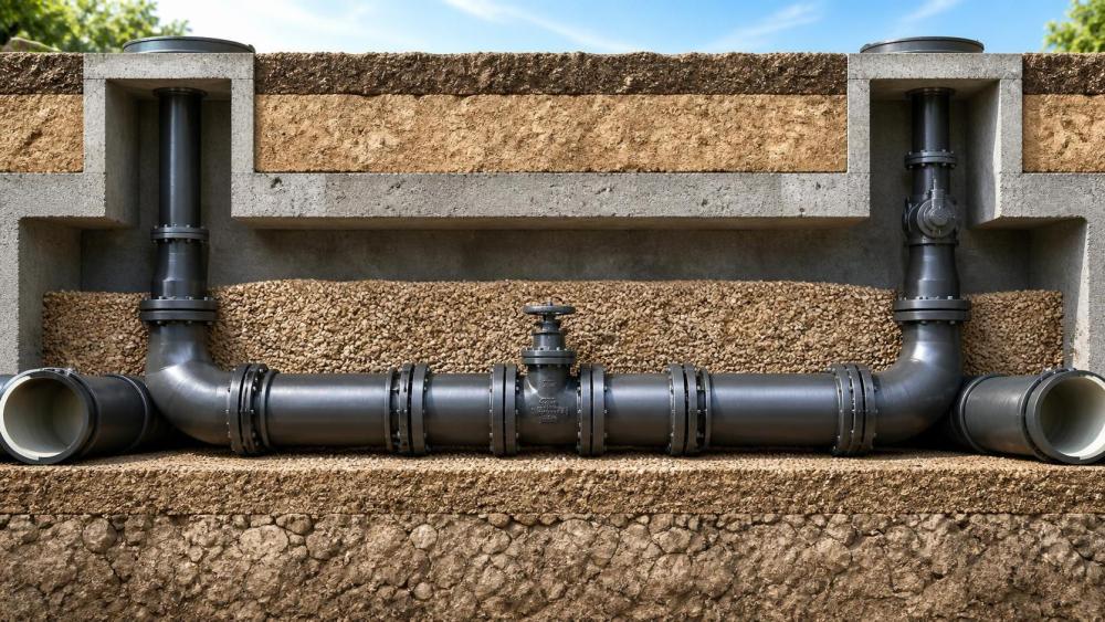
A restrained joint adds a positive mechanical means of resisting separation. Depending on the system, restraint may be created by locking segments, wedges, gripping rings, welded beads, bolts, gland arrangements, or proprietary locking features. The design objective is to maintain continuity between pipe lengths and fittings so that axial forces can be distributed through a restrained pipe length rather than concentrated at one fitting or joint.
This is particularly important at bends, tees, reducers, dead ends, valves, hydrants, and transitions. Under internal pressure, these components generate thrust forces. In stable soil, conventional concrete thrust blocks may resist those forces effectively. In seismic conditions, however, a block can shift, soil resistance can degrade, or the pipeline can move independently of the block. Restrained joints provide a more reliable load path when designed for the actual pressure and ground conditions.
Restraint is not a substitute for flexibility. A pipeline that is fully restrained over long distances can attract axial forces created by ground displacement, settlement, or temperature changes. In locations expected to experience substantial differential movement, the design may need selected flexible joints, special crossing details, casing considerations, expansion or slip provisions, or a purpose-designed seismic coupling. The correct strategy is often a controlled combination of restraint and flexibility rather than maximum restraint everywhere.
Define the pipe and lining requirements separately
Ductile iron pipe is selected in water infrastructure because it offers high structural strength, pressure capability, impact resistance, and well-established installation practice. Pipe dimensions, pressure class or thickness design, and manufacturing requirements should be tied to the applicable project standard. In North American specifications, ANSI/AWWA C151/A21.51 is commonly referenced for ductile iron pipe, while ANSI/AWWA C150/A21.50 provides design considerations for thickness selection. Other markets may use ISO 2531, EN 545, or local equivalent requirements.
For a seismic main, wall thickness should not be chosen only from normal operating pressure. The design review should consider maximum operating pressure, surge pressure, test pressure, installation loading, external earth and traffic loads, and any additional stresses expected from the seismic analysis. A higher pressure class may be justified in critical segments, but simply increasing barrel thickness will not correct an under-designed joint, fitting, or transition.
The cement mortar lining has a separate purpose. It provides an internal barrier that limits corrosion and tuberculation, helps preserve hydraulic capacity, and supports long-term water quality management when properly manufactured and installed. ANSI/AWWA C104/A21.4 is the common North American reference for cement-mortar lining for ductile iron pipe and fittings. The specification should identify the applicable lining standard, required lining condition at delivery, repair procedures for damage, and acceptance criteria for cut ends and field modifications.
Cement mortar lining should not be described as external corrosion protection. It does not address aggressive soil, stray-current exposure, marine influence, or external coating damage. External protection must be evaluated independently through soil investigation and corrosion assessment. Depending on local conditions, this may involve polyethylene encasement, enhanced coatings, cathodic protection, special backfill, electrical isolation measures, or a combination of methods. The appropriate solution depends on measured soil resistivity, pH, chlorides, sulfides, moisture conditions, and the utility’s corrosion-control policy.
Make restrained-joint performance measurable in the specification
“Restrained joint” is too broad to function as a complete requirement. Different manufacturers use different mechanical configurations, allowable deflections, pressure ratings, restraint capacities, and assembly procedures. A procurement document should require the supplier to state the exact joint system proposed for each pipe diameter and fitting type, rather than allowing a generic declaration of compliance.
At a minimum, the submittal should show:
- the joint type and the compatible pipe, fitting, valve, and transition components;
- the maximum rated working pressure and the pressure basis used for restraint calculations;
- the available axial restraint capacity at the specified diameter and joint configuration;
- allowable joint deflection under restrained conditions;
- the required insertion depth, locking procedure, torque requirements where applicable, and field verification method;
- the maximum permissible joint gap and the consequences of over-insertion or under-insertion;
- compatibility with field-cut pipe, beveling requirements, and repair procedures;
- independent or manufacturer-supported test documentation relevant to the required performance.
The design engineer should calculate the restrained length and load path from each thrust-producing component. This includes bends, tees, reducers, plugs, valves, and nonstandard connections. The calculation must account for design pressure, pressure transients, fitting geometry, soil restraint assumptions, and the selected joint system’s rated capacity. A common field problem is extending restraint only a few pipe lengths from a bend because that was the original visual intent, without confirming whether the actual required restrained length is much longer.
Fittings need particular attention. Ductile iron fittings may follow ANSI/AWWA C110/A21.10 or ANSI/AWWA C153/A21.53, as applicable, but the restraint arrangement at each fitting must be explicitly coordinated. A restrained pipe joint does not automatically make every fitting connection restrained. Glands, follower rings, mechanical joints, flange adapters, valve ends, and fabricated steel connections must all be reviewed as part of the same assembly.
Detail the locations where systems usually become vulnerable
Seismic reliability is often lost at transitions. A ductile iron main may be properly restrained, yet connect to unrestrained PVC, HDPE, steel, concrete pressure pipe, or an older cast iron segment with very different stiffness and movement behavior. These locations require a deliberate transition detail that addresses axial load transfer, electrical isolation where needed, corrosion protection, and permissible differential movement.
Valve chambers and vaults also deserve more engineering attention than they typically receive. Rigid wall penetrations can impose concentrated loads on a moving pipe. The pipe may need a flexible penetration seal, a controlled joint location outside the structure, restrained segments on both sides, or support arrangements that prevent the valve and appurtenances from becoming an unintended anchor point.
Crossings require their own design logic. At bridges, culverts, creek crossings, rail corridors, and casings, the pipe support condition may differ sharply from the adjacent buried main. A restrained ductile iron system can be appropriate, but the details should address support spacing, potential settlement at approach zones, casing spacer compatibility, corrosion exposure, access for inspection, and the effect of differential movement between structures and soil.
Construction controls are part of the restraint system
Restrained-joint performance is highly dependent on installation quality. A correctly designed joint can still fail if the pipe is not fully homed, joint surfaces are contaminated, locking components are improperly seated, bolts are not tightened to the specified procedure, or trench geometry prevents the intended deflection and alignment.
Installation requirements should be coordinated with ANSI/AWWA C600/A21.50 practices where applicable, the joint manufacturer’s current instructions, and project-specific seismic details. The manufacturer’s installation guide should not be treated as a substitute for the contract documents; it should be incorporated into the field quality plan.
Useful hold points include verification of pipe and fitting identification, inspection of cement mortar lining before lowering, confirmation of gasket and restraint component placement, recording of insertion marks, bolt torque checks when relevant, confirmation that joint deflection remains within permitted limits, and photographic records before backfill. For critical mains, it is prudent to require qualified field training before production installation and to inspect the first completed restrained assemblies as a benchmark for the remaining work.
Trench backfill is equally important. Loose, poorly compacted, or unsuitable backfill can reduce lateral soil support and allow excessive pipeline movement. Conversely, oversized rock placed against the barrel can damage coatings or create point loading. The geotechnical recommendation should identify suitable embedment material, compaction requirements, groundwater management, and treatment of unstable trench bottoms. These requirements should not be copied unchanged from a routine non-seismic utility project.
Procurement should test system completeness, not only unit price
When sourcing cement mortar lined ductile iron pipes with restrained joint systems, price comparisons can be misleading if bidders are not offering the same level of restraint coverage, fittings, testing records, coating protection, or field support. A lower pipe price can produce a higher installed cost if special components have long lead times, field-cutting is restricted, or the proposed system requires extensive supplemental restraint hardware.
Bid evaluations should distinguish between pipe supply and a complete restrained pipeline package. The latter may include restrained pipe lengths, restrained fittings, mechanical-joint restraint devices, valves with compatible ends, transition couplings, repair components, corrosion-protection materials, installation tools, and technical support. The proposed bill of materials should be reconciled against the restraint schedule and pipeline drawings before award.
Traceability is another practical issue. Require clear identification of pipe class, heat or lot information where specified, lining and coating records, joint component identification, hydrostatic test documentation, certificates of compliance, and shipping records that preserve lot separation. For cross-border procurement, confirm the governing standard edition, documentation language, third-party inspection requirements, packing method, port handling constraints, and responsibility for damaged lining or coating discovered after delivery.
A resilient specification is a coordinated design decision
The strongest specification does not simply call for ductile iron pipe, cement mortar lining, and restrained joints in one sentence. It defines the seismic design basis, identifies the locations requiring restraint or controlled flexibility, sets measurable joint-performance requirements, coordinates fittings and transitions, addresses internal and external corrosion separately, and establishes installation verification procedures.
For water mains that must remain serviceable after disruptive ground movement, the practical objective is continuity: continuity of pressure containment, continuity of load transfer, continuity through fittings and structures, and continuity of construction quality from the mill to final backfill. Cement-mortar-lined ductile iron pipe with a properly engineered restrained-joint system can support that objective effectively, but only when its role is specified as part of the whole pipeline system rather than treated as an interchangeable product feature.
Related News
- Using Industrial Air Blow Guns to Clear Chips Without Spreading DebrisOct 15, 2026Fluid Power Control Strategist
- Ductile Iron Pipe Valves: Which AWWA Standards Apply to Water Main Projects?Oct 15, 2026Dr. Elias Vance
- Why Vacuum Suction Cups Lose Grip on MDF in Woodworking MachinesOct 15, 2026CNC Kinematics Architect
- Choosing a Variable Displacement Piston Pump Manufacturer: What to VerifyOct 15, 2026Fluid Power Control Strategist
- Parallel vs. Angular Pneumatic Grippers for Confined Assembly StationsOct 15, 2026Fluid Power Control Strategist
- Die Castings vs. Investment Castings: Which Costs Less at Your Production Volume?Oct 14, 2026Foundry Phase-Change Fellow