
Selecting Ductile Iron Water Pipes for Municipal Networks: Pressure, Soil, and Joints
Select pipe class only after the full hydraulic envelope and burial environment have been defined. A ductile iron main can have adequate wall strength for normal static pressure yet still be poorly specified if pump transients, unstable trench support, restrained fittings, contaminated soil, or joint deflection were treated as separate issues. Municipal networks operate as systems: pressure events travel through the line, soil loads act continuously, and joints determine whether the installed route can accommodate movement without leakage or pullout.
The starting point is therefore a route-based selection, not a catalog-based selection. Divide the proposed line where operating pressure, elevation, pumping arrangement, soil condition, cover depth, traffic loading, groundwater, or connection layout changes. A single nominal diameter may remain suitable across those sections, while pipe class, lining, external protection, joint type, and restraint requirements do not.
Establish the pressure envelope before selecting pipe class
Working pressure is the sustained internal pressure expected during normal service. It is essential, but it is not the design peak. Pressure varies along a transmission main because elevation changes alter static head, pump duty changes alter discharge pressure, and control arrangements introduce local losses. The lower portions of a gravity-influenced route can see considerably higher pressure than high points, even when the same pump station supplies both areas.
Surge pressure must be assessed alongside working pressure. Rapid pump trip, sudden valve closure, power loss, check-valve response, air release behavior, and emergency isolation can create transient pressure above routine operating conditions. The severity is related to fluid velocity, pipe length, wave behavior, valve closure time, and the actual response of pumps and appurtenances. Treating surge as a simple percentage added to normal pressure is unreliable when a long rising main, multiple pumps, or fast-acting controls are involved.
A useful pressure schedule identifies, for each section, normal minimum and maximum pressure, anticipated transient high pressure, and any vacuum or sub-atmospheric condition. Negative pressure deserves separate attention. A pipe wall selected for internal pressure does not automatically resolve collapse risk where a drained line, pump shutdown, blocked air valve, or rapid emptying event can create vacuum. Air valves, operating procedures, and pipe stiffness should be considered together rather than assigning the problem solely to the pipe barrel.
Pressure designation alone should not be read as a complete statement of field capacity. Fittings, valves, flanged connections, couplings, restrained joints, hydrant branches, and transition assemblies must be evaluated at compatible pressure levels. A pressure-resistant barrel connected through an inadequately rated flange or improperly restrained bend remains a weak system.
Soil conditions affect both external loading and corrosion protection
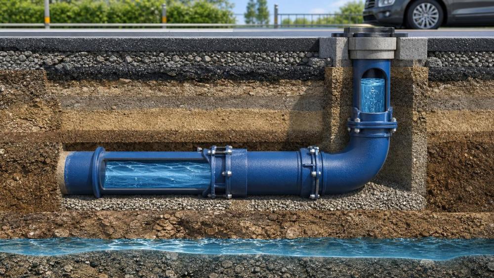
Ductile iron pipe performs well under buried loads because its ring stiffness, strength, and installation behavior differ from more flexible pipe materials. Still, external load capacity is not determined by pipe class in isolation. Trench width, bedding quality, side support, compaction, depth of cover, groundwater, and traffic loading influence how load reaches the barrel. Poor haunch support can concentrate load and permit differential settlement, while a well-shaped bedding envelope distributes it more predictably.
Existing utility corridors create a frequent blind spot. A replacement main may pass beneath paved streets where cover is deep, cross former excavations with variable backfill, and enter constrained zones beside structures. The soil description from one borehole or a general geotechnical summary may not represent the entire alignment. Identify zones of soft ground, uncontrolled fill, rock, aggressive runoff, high water table, and potential future excavation before locking the pipe schedule.
External corrosion selection requires a soil investigation that is meaningful for metallic pipe, rather than a generic statement that ground is “wet” or “clayey.” Relevant indicators can include soil resistivity, pH, moisture condition, redox behavior, sulfides, chlorides, stray-current exposure, and the presence of cinders, industrial fill, or dissimilar buried metals. No single result defines corrosivity. Low resistivity is a warning sign, but it should be interpreted with the broader soil and installation context.
Protection measures should match the mechanism being controlled. An external polyethylene encasement is commonly considered where corrosive soil is a concern, but its effectiveness depends on continuity, proper overlap, intact material, and avoiding tears during placement and backfill. Coatings and enhanced protective systems need equal attention at cut ends, fittings, service connections, and repair locations. Those discontinuities are where otherwise sound corrosion strategies are often compromised.
Internal lining addresses a different exposure. Potable water chemistry, suspended solids, flow velocity, stagnation periods, and disinfection practice influence lining selection and long-term hydraulic behavior. A lining suitable for clean treated water may require reconsideration when the conveyed fluid is abrasive, chemically variable, or associated with wastewater service. External soil protection and internal lining should therefore appear as separate decisions in the specification, even though both are casually described as “corrosion protection.”
Choose joints by movement, restraint, and access requirements
Push-on gasketed joints are widely used because they permit efficient assembly and controlled angular deflection. Their value lies in accommodating ordinary route changes and modest settlement without forcing every deviation into a fabricated bend. The stated deflection allowance is not a license to bend the route arbitrarily. Deflection must be distributed over several joints where appropriate, remain within the applicable joint limit, and preserve correct gasket seating.
Joint deflection and trench geometry interact. A tight curve may look feasible on a plan using nominal joint deflection, yet become difficult where the trench is narrow, the barrel is short near a fitting, or joint orientation is constrained by an existing utility. Excessive angularity can make insertion difficult, damage a gasket, reduce engagement, or leave insufficient room for installation equipment. Route curves should be set out from the actual pipe lengths and fitting dimensions, not from a simplified centerline alone.
Restrained joints are selected where internal thrust or external movement could separate a standard joint. Bends, tees, reducers, dead ends, valves, vertical offsets, and connections to other pipe materials commonly require a thrust-resistance design. Restraint can be provided through restrained-joint assemblies, thrust blocks, or a combination, but the method must be compatible with the site. A concrete thrust block depends on bearing against stable undisturbed soil; placing it in soft fill, saturated ground, or a future excavation zone may not provide the assumed reaction.
Restrained length is not interchangeable with “a few restrained pipes near the fitting.” It is derived from pressure, pipe diameter, fitting angle, soil resistance, depth, and the capacity of the selected restraint system. Direction matters as well. A horizontal bend, a vertical offset, and a branch connection mobilize resistance differently. Where the line crosses a bridge approach, enters a casing, passes through a structure wall, or connects to a valve chamber, pullout resistance and movement allowance deserve explicit review.
Details that prevent joint-related rework
- Confirm spigot insertion depth with the applicable assembly mark. Under-insertion reduces the intended engagement; over-insertion can limit movement space or distort alignment at the next joint.
- Keep bell interiors, gaskets, and spigot ends clean until assembly. Soil, stones, dried coating debris, or damaged gasket grooves can cause leakage that is hard to diagnose after backfill.
- Use approved lubricant in the required quantity and place the gasket evenly. A rolled or displaced gasket may pass initial visual checks yet leak during pressure testing.
- Maintain pipe support close to the joint during make-up. Dragging a spigot through trench material can scar the sealing surface or introduce angular misalignment before the joint is seated.
- Document field cuts, repairs, and transitions. A cut end needs the correct finishing treatment and joint arrangement; it should not be treated as equivalent to a factory-prepared spigot.
Connections deserve particular scrutiny because municipal renewals rarely consist of uninterrupted new pipe. Transition couplings, flange adaptors, mechanical joints, and connections to legacy mains must accommodate actual outside diameters, ovality, surface condition, restraint needs, and available installation clearance. “Same nominal size” does not confirm compatibility between pipe generations or materials. Field measurement before ordering special transition components avoids a common source of delay.
Installation assumptions need to be written into the selection
A pipe schedule that omits construction conditions leaves critical engineering choices to field interpretation. State the allowable cover range, bedding material and thickness, compaction expectations, trench width limits where relevant, rock excavation treatment, handling restrictions, and protection at crossings. These instructions should align with the structural assumptions used for design. Increasing cover, widening a trench, or substituting native spoil for specified embedment can change pipe support even when the barrel itself is unchanged.
Handling and storage also affect the delivered system. Pipes should be supported to prevent localized damage, and lifting methods should avoid uncontrolled contact at bells, linings, and coating surfaces. Fittings need their own inspection because geometry, joint configuration, and protective treatment can differ from straight pipe. Before lowering materials into the trench, inspect for cracks, damaged lining, coating holidays, contaminated gasket seats, and deformation at connection ends.
Hydrostatic testing should be planned before the first section is installed, not treated as a final administrative event. Test section length, filling rate, air removal points, temporary end restraint, pressure measurement location, allowable test criteria, and access for correcting leaks all influence the result. Entrapped air can distort test observations and create unsafe stored energy. A failed test may originate at a temporary connection, valve, gasket, or test setup rather than the pipe barrel, so fault isolation should proceed methodically.
Build a specification around interfaces, not isolated components
The most reliable selection documents connect the hydraulic model, profile drawing, geotechnical information, corrosion assessment, valve schedule, thrust design, and installation method. Each document answers a different question, but contradictions between them are costly. A profile may show a high point without an air-valve arrangement; a fitting schedule may omit restraint; a corrosion note may cover straight pipe but not fittings; a pressure class may be specified without stating the transient condition behind it.
Request traceable technical submittals for pipe, fittings, gaskets, linings, external protection, and restraint components. Review dimensions, joint types, pressure capabilities, coating or encasement details, and installation instructions as one assembly. Material documentation has practical value when it can be tied to the delivered lot and to the specified system, rather than filed as a disconnected certificate.
Selection is complete when the intended pipe class carries the defined hydraulic loads, the protection system matches the actual environment, the joints accommodate route movement, and thrust has a continuous load path into competent support or engineered restraint. That alignment produces a pipe system suited to the route it will serve, rather than a collection of individually acceptable components.
Related News
- How to Assess a Rigid Coupling Supplier for Bore Accuracy and Traceable QualityOct 08, 2026Tribology & Kinematics Expert
- Titanium Alloys Compared: Balancing Strength, Corrosion Resistance, and MachinabilityOct 08, 2026CNC Kinematics Architect
- Where Ductile Iron Dismantling Joints Reduce Alignment Risk in Water PipelinesOct 08, 2026Pipeline Metallurgy Scientist
- Selecting a Precision Bearing Sleeve: Fits, Runout, and Material ChoicesOct 08, 2026Tribology & Kinematics Expert
- Face Milling Cutters: How Insert Geometry Affects Finish on Steel and AluminumOct 08, 2026CNC Kinematics Architect
- Single-Acting Cylinders for Clamping: Stroke, Force, and Return Spring ConsiderationsOct 07, 2026Fluid Power Control Strategist