
Ductile Iron Pipes for Municipal Water Mains: Selecting Class, Lining, and Joints
Start With the Duty of the Main, Not the Pipe Catalog
For a municipal water main, ductile iron pipe selection should begin with the operating duty of the pipeline: the pressure it will see, the ground it will cross, the connections it must make, and the consequences of a failure. Diameter alone does not establish a suitable specification. A pipe that performs well on a short, low-pressure distribution extension may be under-designed for a pumped transmission main, a road crossing, or a line exposed to aggressive soil.
The practical selection sequence is usually class first, then lining and external protection, then the joint system. These decisions interact. A heavier pipe class may be justified by surge pressure or installation loads; a more resistant lining may be needed because of water chemistry; and a restrained joint may alter how the pipeline manages thrust, settlement, and access constraints. Treating each item as an isolated catalog choice often creates gaps between hydraulic design, civil design, and construction reality.
For project managers, the objective is not to specify the heaviest available pipe or the most elaborate protection package throughout the route. It is to identify where the system needs additional margin, where standard arrangements are adequate, and where the design must account for unusual site conditions before materials are ordered.
Choose Pipe Class From Combined Loads
Pipe class is commonly discussed as a pressure decision, but municipal mains are exposed to more than steady internal pressure. The selected class needs to accommodate the combined effects of normal operating pressure, transient events, installation depth, traffic loading, handling, and bedding support. In some routes, external loading or construction conditions can influence the choice as much as internal pressure.
The first design input is the expected operating pressure range. This should reflect the actual hydraulic zone, pump operating conditions, pressure-reducing arrangements, and likely future operating scenarios. A main that is currently supplied by gravity may later be connected to a booster station or reconfigured as part of a pressure-zone upgrade. Where that possibility is credible, it belongs in the design basis rather than being treated as a future contractor issue.
Surge pressure requires separate attention. Valve closures, pump starts and stops, power interruptions, air release behavior, and rapid changes in demand can all create short-duration pressure events that are materially higher than normal static or working pressure. Selecting pipe only from a normal-pressure value can leave limited allowance for these events. The hydraulic analysis should establish the expected transient envelope and identify whether surge control measures, a higher pipe class, or both are needed.
External conditions then need to be overlaid on the route. Consider:
- Depth of cover, including localized deeper sections at crossings and utility conflicts.
- Permanent and temporary traffic loads, particularly beneath major roads, bus routes, industrial access roads, and construction haul routes.
- Native soil bearing capacity and the quality of proposed bedding and haunch support.
- Potential for trench-wall instability, uneven backfill compaction, or loss of support caused by groundwater movement.
- Installation methods such as open trench, casing installation, shallow cover, or constrained urban excavation.
Ductile iron has substantial structural strength, but that does not remove the importance of trench design. Pipe stiffness alone cannot compensate for poorly prepared bedding, voids at the haunches, sharp rock contact, or inconsistent compaction. A pipe class decision should therefore be reviewed alongside the civil specification, not handed over as a purely mechanical selection.
One frequent error is applying a single conservative class across an entire project to simplify procurement. That can be reasonable where route conditions are broadly uniform and schedule risk outweighs material optimization. It is less defensible on long projects with distinct pressure zones, varying cover depths, or isolated high-load crossings. Segmenting the specification can reduce unnecessary weight and handling burden while directing higher-class material to the locations that actually require it. The tradeoff is added control: drawings, material schedules, delivery markings, and field inspection must make the transitions unambiguous.
Internal Lining Is a Water Quality and Operating Decision
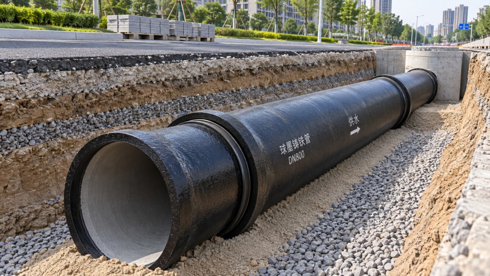
The internal lining of Ductile Iron Pipes is often treated as a default item, yet it has a direct relationship with hydraulic performance, water quality management, and the long-term condition of the main. The correct question is not simply which lining is available. It is what the conveyed water, treatment process, and operating regime are likely to demand over the life of the asset.
Cement mortar lining is widely used for potable water mains because it provides a protective barrier between the water and the iron surface and can support stable hydraulic conditions when properly applied and handled. For many municipal water applications, it is an appropriate and established baseline. However, it should not be assumed to solve every internal corrosion or water-quality concern.
Water chemistry can change the selection. Factors such as pH, alkalinity, hardness, dissolved constituents, disinfectant strategy, temperature, and stagnation periods may affect how a lining performs over time. Blended sources, seasonal source changes, desalinated water, aggressive groundwater entering a system through defects, and process water applications deserve particular review. Where chemical conditions are outside the normal range for a standard lining, the project team should define the required resistance and consult the relevant pipe, lining, and water-quality requirements before fixing the specification.
Flow regime also matters. A high-velocity transmission main, a low-turnover dead-end extension, and a line that is routinely drained and refilled do not impose the same internal conditions. Abrasion can be a concern where water carries suspended solids. Intermittent service can increase the relevance of drying, wetting, and disinfection cycles. In a potable network, the lining decision must remain consistent with the utility’s water-quality objectives and approved material requirements.
Project teams should avoid an assumption that a lining is an interchangeable add-on. Its performance depends on production quality, curing, handling, cutting, field repairs, and the treatment of exposed ends or fittings. A detailed submittal review should establish the lining type, application standard, thickness requirements where applicable, repair method, compatibility with fittings and valves, and acceptance criteria for damaged material. Those details become especially important where pipes will be stored for extended periods, cut frequently in the field, or installed in complex valve chambers.
External Protection Must Follow the Soil Investigation
External corrosion protection should be driven by route-specific soil and groundwater conditions. Ductile iron’s mechanical performance does not make it immune to corrosive environments, and external protection should not be selected solely from general assumptions about a municipality or region. Conditions can vary sharply within one project: reclaimed land, coastal zones, industrial districts, wetland crossings, made ground, and areas affected by stray current may require different treatment from ordinary native soil.
The geotechnical and corrosion review should identify the properties relevant to pipe durability, including soil resistivity, moisture, pH, chlorides, sulfides, redox conditions, and groundwater characteristics where applicable. The point is not to collect every possible laboratory result. It is to establish whether the route presents conditions where standard external coatings are sufficient or whether supplemental protection should be considered.
Protection measures can include appropriate factory-applied coatings, polyethylene encasement, enhanced coating systems, careful backfill selection, or more specialized corrosion-control measures where justified by the environment. The appropriate approach depends on the whole installation system. For example, a protective wrap can be compromised by poor application, tears during backfill, or incomplete treatment at fittings and appurtenances. A high-specification coating can still be exposed at field cuts or damaged during unloading if inspection and repair requirements are weak.
There is also a boundary issue that project documents should resolve early: fittings, valves, restrained glands, service connections, and fabricated specials must receive corrosion protection compatible with the pipe system. It is common for a pipe specification to be detailed while adjacent components are covered only by generic wording. That creates a vulnerable transition at locations that are often difficult to excavate after commissioning.
Joint Selection Determines How the Main Handles Movement and Thrust
For buried municipal water mains, joint choice is a structural and construction decision as much as a leakage decision. Push-on joints, mechanical joints, flanged joints, and restrained configurations each have a role, but they transfer loads and tolerate movement differently. The selected joint system must reflect pipeline geometry, soil behavior, thrust locations, access needs, and installation sequence.
Push-on joints are commonly suitable for straight or gently curving buried runs where flexibility during installation is useful and the pipeline is supported by suitable trench conditions. Their deflection capability can help accommodate minor route changes and settlement, within the joint manufacturer’s permitted limits. That flexibility should not be treated as permission to force the route around sharp changes in alignment. Excessive deflection can impair assembly quality, reduce the available movement margin, and make later inspection difficult.
Mechanical joints are often useful at fittings, valves, transitions, repairs, and locations where adjustment is needed during assembly. Their value is practical control, but they require disciplined bolt tightening, gasket placement, and restraint coordination. Uneven tightening or uncontrolled field modifications can create problems that may not be apparent until pressure testing or service.
Flanged joints are generally associated with above-ground installations, chambers, pump stations, and equipment connections where dismantling access is required. They are not a substitute for a buried flexible joint system. Buried flanged assemblies need careful consideration because access for maintenance is limited and movement or corrosion can complicate future intervention.
The largest decision is often whether joints must be restrained. At bends, tees, reducers, valves, dead ends, vertical changes, and other points where internal pressure creates unbalanced force, the main needs a designed thrust-resistance strategy. This may use restrained joints, thrust blocks, or a combination of approaches depending on the route and ground conditions.
A restrained joint design should specify more than the words “restrained joint.” It needs to define the applicable pipe sizes, fitting types, restraint method, design pressure basis, length of restrained pipe on each side of the fitting, and any installation limits. It should also confirm compatibility between the selected pipe, fitting, gland, gasket, coating, and external protection arrangement. Mixed components can appear compatible at first glance while having different dimensional, coating, or restraint requirements.
Coordinate the Specification Before Procurement
The procurement package should convert the engineering decisions into requirements that can be inspected at delivery and installation. This is where many avoidable disputes begin: drawings refer to a pipe class, schedules list another designation, and contractor submittals offer a technically plausible alternative without demonstrating that it satisfies the full system duty.
A useful submittal review covers the pipe and fittings together. Confirm the governing standard, nominal sizes, class or pressure designation, lining, external coating, joint type, restraint components, gasket materials, fittings, valves, field-cut procedures, repair materials, markings, and traceability documents. Factory testing and material records matter, but so do practical matters such as whether restrained components are supplied as a coordinated system and whether the contractor has a clear installation method for the selected joints.
Delivery planning deserves similar attention. Ductile iron pipe is durable, but coating damage, lining damage, and handling impacts can occur between factory release and final installation. Define unloading practices, storage support, inspection responsibilities, rejection and repair procedures, and segregation of different classes or joint types. On a multi-zone project, physical identification must make it difficult for crews to install a lower-class pipe in a higher-duty section.
The most reliable municipal specifications are usually those that make the design logic visible. They state the hydraulic basis for class selection, identify corrosive or movement-sensitive sections, show where restraint begins and ends, and define the lining and protection expectations for the water and soil conditions involved. That gives the contractor a buildable system, gives procurement a comparable basis for evaluation, and gives the owner a clearer record for future maintenance and renewal decisions.
Related News
- How to Assess a Rigid Coupling Supplier for Bore Accuracy and Traceable QualityOct 08, 2026Tribology & Kinematics Expert
- Titanium Alloys Compared: Balancing Strength, Corrosion Resistance, and MachinabilityOct 08, 2026CNC Kinematics Architect
- Where Ductile Iron Dismantling Joints Reduce Alignment Risk in Water PipelinesOct 08, 2026Pipeline Metallurgy Scientist
- Selecting a Precision Bearing Sleeve: Fits, Runout, and Material ChoicesOct 08, 2026Tribology & Kinematics Expert
- Face Milling Cutters: How Insert Geometry Affects Finish on Steel and AluminumOct 08, 2026CNC Kinematics Architect
- Single-Acting Cylinders for Clamping: Stroke, Force, and Return Spring ConsiderationsOct 07, 2026Fluid Power Control Strategist