
Choosing Fiber Laser Tube Cutting Machines for High-Accuracy Square Tube Fabrication
Choosing Fiber Laser Tube Cutting Machines for High-Accuracy Square Tube Fabrication
Selecting fiber laser tube cutting machines for square tubes requires more than comparing laser power or headline cutting speed. Technical evaluators need to consider how a machine holds the tube, follows its actual geometry, manages heat at corners, and maintains positional accuracy over a production shift. These details determine whether cut parts move directly into welding and assembly or return to secondary operations for deburring, rework, or correction.
Square and rectangular hollow sections are widely used in structural frames, equipment enclosures, material-handling systems, agricultural machinery, vehicle subassemblies, racks, energy equipment, and industrial automation. Their flat faces simplify fixturing and connection design, but their corners introduce cutting and clamping challenges that are less obvious with round tubes. A machine that performs well on standard round stock may not automatically deliver the same consistency on thin-wall square tube, welded profiles, or long members with demanding hole-position requirements.
For this reason, a sound decision begins with the fabricated part rather than the machine catalog. The key question is not simply, “What laser source is installed?” It is whether the complete machine system can repeatedly produce the required geometry from the tube materials, dimensions, and order patterns that the shop actually expects to run.
Define Accuracy as a Part Requirement, Not a Marketing Claim
“High accuracy” can mean several different things in square tube fabrication. A structural fabricator may be mainly concerned with cut length, hole location, mitre consistency, and fit-up at welded joints. An OEM producing modular machinery frames may need more reliable feature-to-feature positioning because holes, slots, tabs, and access openings must align with purchased components. In either case, a quoted positioning specification is only one part of the answer.
Technical teams should translate drawings into measurable acceptance points: overall length, angular tolerance on bevels or mitres, location of holes from a defined datum, slot profile, corner condition, and allowable burr. They should also clarify whether tolerances apply to the first part only or must be sustained across a batch. This distinction matters because drift can result from chuck wear, tube variation, thermal conditions, poor support settings, or unstable material feeding.
The incoming tube itself must be included in the tolerance discussion. Commercial square tube can have straightness variation, twist, wall-thickness variation, weld-seam effects, corner-radius differences, and surface condition issues. A cutting machine cannot remove every effect of inconsistent raw material. It can, however, detect, compensate for, or avoid some of them when its sensing, clamping, and software functions are properly matched to the application.
Why Square Tubes Put More Pressure on the Machine System
A square profile changes the mechanics of tube processing. Chucks must grip flat-sided material securely without excessive deformation, particularly on lighter-wall sections. During rotation, poor clamping can cause slippage or positional error. If the profile is not centered consistently, holes or contours on adjacent faces may shift relative to one another even when the linear axes are performing correctly.
Corners also affect cut quality. The laser head must maintain suitable stand-off distance as it passes from a flat face around a corner radius, while the control system adjusts motion and process parameters. Thin material can be vulnerable to heat distortion; thicker material may demand stable gas delivery and reliable piercing behavior. The best result is not necessarily the fastest programmed cycle. It is the cycle that produces acceptable edges and geometry without creating an unpredictable downstream workload.
Long workpieces add another variable. Tube sag, vibration, and movement during unloading can influence consistency, especially when features are cut near the ends of long sections. Support systems, follow-up rests, and unloading arrangements deserve the same technical attention as the laser source. A machine that is accurate in a short demonstration may behave differently when processing full-length square tubes under normal production handling.
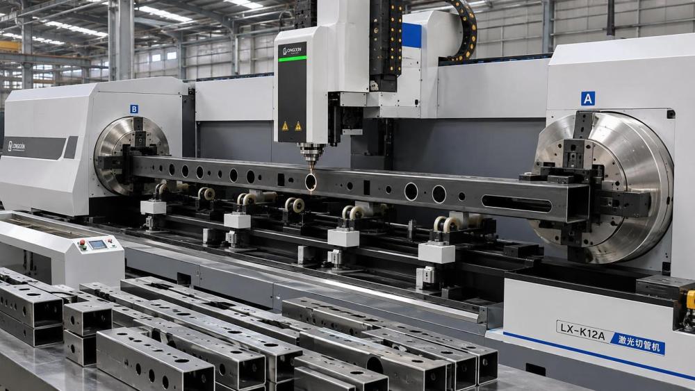
Assess the Chuck, Support, and Loading Arrangement Together
The clamping architecture is one of the most consequential considerations when evaluating fiber laser tube cutting machines for square tubes. Review the supported profile range, minimum and maximum wall conditions, clamping method, rotation control, and the ability to manage profiles that are not perfectly straight. Ask how the machine establishes the tube datum and whether the setup changes when moving among square, rectangular, round, channel, or other permitted profiles.
Rear and front chuck coordination is particularly important for cut-length control and remnant management. If material utilization is a priority, understand the machine’s practical tailing length for the relevant square tube sizes, rather than relying on a general statement about “zero tail” or reduced waste. The usable remnant depends on the profile, the clamping sequence, required feature locations, and the need to keep the part stable during final cuts.
For high-mix fabrication, automatic loading can reduce manual handling and improve repeatability, but it also introduces questions about bundle quality, tube separation, length variation, and transfer reliability. Semi-automatic loading may be adequate for a shop running short batches or frequent profile changes. Full automation is more justified where production volume, staffing constraints, and scheduling discipline can support it. Automation should be evaluated as a material-flow decision, not as an automatic sign of better cutting quality.
Laser Power Should Follow the Material Mix
Laser power influences cutting capacity, but choosing the highest available power without reference to the expected production mix can raise capital cost, energy demand, and process complexity without solving the actual bottleneck. The appropriate source configuration depends on material type, wall thickness, feature complexity, acceptable cycle time, and how often the machine will process reflective metals or difficult geometries.
A shop focused on thin-wall carbon steel frames has different needs from a manufacturer cutting thicker stainless steel members, galvanized material, aluminum profiles, or mixed material batches. Piercing performance, edge oxidation, dross tendency, and gas consumption should be assessed on representative samples. It is also worth separating straight cutting speed from overall part throughput. Frequent pierces, small holes, narrow slots, and contour changes can make motion control and process tuning more influential than raw speed on a simple straight line.
Assist gas selection belongs in this review. Oxygen, nitrogen, air, or other process choices may be appropriate depending on material and finish requirements, but their impact extends beyond cut quality. Gas supply infrastructure, purity requirements where applicable, operating cost, safety arrangements, and local availability can all affect the long-term operating model. These points should be confirmed against the intended parts and local plant conditions rather than treated as generic machine options.
Software Determines Whether Complex Tube Parts Are Practical
The cutting head is visible; software capability is often where the production advantage is decided. Square tube programs may include holes on multiple faces, interlocking tabs, copes, mitres, drainage openings, access cutouts, and assembly marks. The programming environment should import the drawing formats used by the engineering team, create reliable tube features, support nesting, and provide a clear route from design revision to released shop program.
Evaluators should ask how the system handles corner transitions, weld seams where relevant, lead-ins and lead-outs, collision avoidance, and common-cut strategies. A useful simulation should show not only the laser path but also chuck movement, support movement, material rotation, and part drop behavior. This is especially valuable when a fabricated frame includes many openings close to one another or near an end where stability changes.
Integration with upstream CAD, ERP, MES, or production planning systems may matter in larger operations, but the practical workflow should remain understandable to programmers and operators. A highly capable system that requires complex intervention for ordinary jobs can become a source of delay. Conversely, simplified templates can be effective for repeat work but may limit engineering flexibility. The right balance depends on the volume of repeat parts versus engineered-to-order fabrication.
Run a Representative Acceptance Test Before Final Selection
A machine comparison is strongest when suppliers are asked to process the same representative drawings and materials. The test package should include the square tube sizes that matter commercially, not only a convenient demonstration profile. If the business expects mixed wall thicknesses, galvanized sections, stainless grades, long members, or parts with closely spaced features, those conditions should be present in the evaluation.
Inspection should go beyond visual appearance. Measure cut length, hole-to-hole position across faces, angular features, slot dimensions, and edge condition at corners. Review whether the parts fit their intended weld fixture or assembly interface. If a secondary process is normally required, identify whether it is necessary for functional reasons or whether the proposed cutting setup is creating avoidable work.
Look Beyond the Machine’s First Year of Operation
Maintenance access, local service coverage, operator training, spare-parts availability, and remote diagnostic capability should be examined before purchase. A tube laser is a coordinated system of optics, motion components, controls, chucks, extraction equipment, safety devices, and material handling. Downtime can stem from any of these areas, not only from the laser source.
Ask the supplier to define routine maintenance tasks, recommended inspection intervals, consumable categories, and the responsibilities of the customer versus the service provider. Also confirm site requirements: electrical supply, compressed air quality, assist gas arrangements, extraction, floor loading, clearance for loading and unloading, and safety compliance applicable to the installation location. These are not minor implementation details. A poorly prepared site can compromise commissioning and delay production readiness.
Documentation matters when the fabricated parts enter regulated, safety-sensitive, or contract-controlled supply chains. Drawings, material certificates, inspection records, machine maintenance logs, and program revision control may all form part of the customer’s quality expectation. The machine does not create a complete quality system, but it should fit the organization’s traceability and inspection practices without forcing excessive manual work.
Make the Decision Around the Full Fabrication Route
The most suitable fiber laser tube cutting machine is not always the one with the broadest specification. It is the one that supports the required square tube range with stable accuracy, predictable edge quality, manageable programming, and a material-flow arrangement that fits the shop. Its value is often visible in reduced drilling, sawing, milling, marking, manual layout, and weld-fixture adjustment—not merely in faster laser cutting.
For technical evaluators, the practical path is to establish part-family requirements, validate them with representative tests, inspect the whole handling and software workflow, and then compare lifecycle support obligations. This approach is consistent with the broader industrial perspective used by Global Industrial Machining & Piping Equipment Network (IMPE): equipment performance must be considered alongside material behavior, tolerances, inspection methods, and the final function of the fabricated assembly.
Before committing to a machine configuration, confirm the actual tube drawings, material supply condition, required quality records, site utilities, expected production mix, and after-sales response model. Those details will usually reveal more about long-term suitability than a comparison of laser power alone.
Related News
- How to Assess a Rigid Coupling Supplier for Bore Accuracy and Traceable QualityOct 08, 2026Tribology & Kinematics Expert
- Titanium Alloys Compared: Balancing Strength, Corrosion Resistance, and MachinabilityOct 08, 2026CNC Kinematics Architect
- Where Ductile Iron Dismantling Joints Reduce Alignment Risk in Water PipelinesOct 08, 2026Pipeline Metallurgy Scientist
- Selecting a Precision Bearing Sleeve: Fits, Runout, and Material ChoicesOct 08, 2026Tribology & Kinematics Expert
- Face Milling Cutters: How Insert Geometry Affects Finish on Steel and AluminumOct 08, 2026CNC Kinematics Architect
- Single-Acting Cylinders for Clamping: Stroke, Force, and Return Spring ConsiderationsOct 07, 2026Fluid Power Control Strategist