
CNC Lathes Explained: Matching Turning Capacity to Production Requirements
A CNC lathe should be selected around the parts it must produce repeatedly, not around the largest number on a machine brochure. A turning center with a generous swing diameter may still be a poor fit if the bar capacity is too small, the spindle lacks torque for the material, the turret cannot carry the required tools, or part handling takes longer than the cutting cycle.
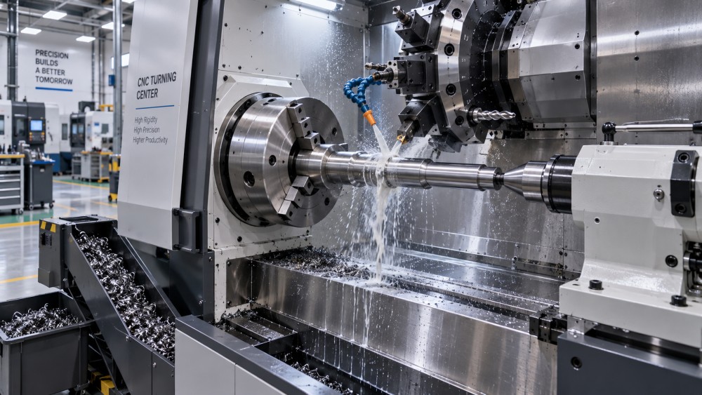
CNC lathes produce rotational parts by holding and rotating a workpiece while cutting tools remove material. They are used for shafts, bushings, flanges, threaded fittings, collars, pins, hubs, valve components, bearing seats, hydraulic parts, and many other components with cylindrical, tapered, grooved, or threaded features. Modern machines can also drill, mill, cross-drill, and machine off-center features, but their core value remains efficient and controlled turning.
The practical question is not simply, “What size lathe is needed?” It is: Can this machine hold, machine, measure, and move the full range of parts at the required quality and output? Turning capacity is the combined result of physical workspace, spindle capability, workholding, tooling, control functions, automation, and inspection discipline.
Start with the finished part, then work backward
A drawing is the correct starting point, but the finished outside diameter alone is not enough. The relevant dimensions include raw stock size, finished length, overhang beyond the chuck, internal bore requirements, and any feature that must be machined in a second setup. A forged shaft, for example, may arrive with uneven stock allowance and require substantially more clearance than its finished drawing dimensions suggest. A thin-wall tube may fit easily inside the machine envelope but still be difficult to clamp without distortion.
For each representative part family, identify:
- Maximum raw and finished diameter
- Maximum part length, including holding allowance
- Part weight and how it will be loaded
- Bar-fed, chuck-held, collet-held, or fixture-held production method
- External and internal features, including threads, grooves, bores, and tapers
- Material condition, such as free-machining steel, stainless steel, cast iron, aluminum, or heat-treated alloy
- Required tolerances, surface finish, and inspection points
- Expected batch size and frequency of changeover
This process avoids a common selection error: choosing a machine that accommodates the nominal part but leaves little room for jaws, tools, probes, tailstock support, chip evacuation, or operator access.
What turning capacity actually includes
Machine specifications can look straightforward, yet each capacity figure has a specific meaning. Reading them in isolation can lead to an inaccurate comparison.
A large swing is especially easy to overvalue. It indicates that a large workpiece can physically rotate, but production machining also needs clearance for jaws, cutting tools, toolholders, coolant nozzles, and sometimes a tailstock or steady rest. The usable capacity for a large flange or ring can therefore be meaningfully lower than the headline swing figure.
Diameter, length, and support must be considered together
Short, large-diameter parts and long, slender shafts place very different demands on CNC lathes. A compact chucking lathe may be highly productive for flanges, valve bodies, hubs, and hydraulic fittings, while a long shaft requires attention to rigidity and support.
As a workpiece becomes longer relative to its diameter, deflection and vibration become more likely. Cutting forces can push the workpiece away from the tool, producing taper, chatter marks, inconsistent diameters, or poor surface finish. The issue is not solved merely by selecting a machine with sufficient bed length. The production method may require a tailstock, a programmable steady rest, special jaws, center holes, or several machining stages.
For a shaft with critical bearing seats, the holding strategy deserves the same attention as the lathe itself. If the component will be turned between centers, the machine must support that process. If it is clamped in a chuck, the clamping length, jaw design, and unsupported extension must be evaluated. A machine may have ample length capacity but still be unsuitable if the planned setup cannot keep the part stable.
Spindle power is not the same as useful cutting performance
Spindle speed often attracts attention because it is easy to compare. High speed can improve productivity on small-diameter aluminum, brass, and certain steel components, particularly where many short cycles are involved. It is less meaningful when turning large diameters, heavy forgings, castings, or tough alloy materials.
At larger diameters, the workpiece surface moves quickly even at a relatively low spindle speed. The machine needs torque to maintain the selected cutting load without slowing or becoming unstable. Heavy roughing of a forged shaft or a cast pump component may demand a rigid structure, strong spindle torque, secure workholding, and dependable chip control more than very high maximum rpm.
Material condition changes the calculation as well. A soft material can create long, tangled chips. Stainless steel may generate heat and promote tool wear if the process is not stable. Interrupted cutting on a casting or forging can stress inserts and workholding. Heat-treated material may require different tooling, lighter passes, or a grinding operation for the most demanding surfaces. The appropriate machine is therefore linked to the complete route sheet, not only to a material name on the drawing.
Tooling capacity determines whether a part stays in one setup
Many parts that appear to be simple turned components include drilled holes, internal threads, radial holes, milled flats, keyways, or bolt-circle features. A basic two-axis lathe can produce the turning features, but secondary operations may be needed elsewhere. That can be sensible for low-volume work, especially where a milling machine is already available. It becomes less attractive when extra handling threatens positional accuracy, lead time, or labor efficiency.
A turning center with live tooling and a C-axis can perform selected milling and drilling operations while the part remains clamped. This can reduce setups and improve feature-to-feature alignment. A Y-axis adds further flexibility for off-center work, though it also increases machine complexity, programming requirements, and investment. It should be selected because the part mix needs it, not because it is generally perceived as more advanced.
Tool station count matters for another reason: process continuity. A production cycle may need roughing tools, finishing tools, boring bars, drills, threading inserts, grooving tools, cutoff tools, and redundant tools for long runs. If the turret is crowded, operators may compromise the process, change tools during production, or split work across operations. Those decisions affect throughput more than a marginal difference in rapid-traverse speed.
Choose the machine architecture around the production pattern
Different forms of CNC lathes suit different part flows. The correct architecture depends on how parts enter the machine, how many operations they require, and how frequently the setup changes.
Chucking lathes for flexible medium and large workpieces
Chucking lathes are commonly used for castings, forgings, cut blanks, flanges, valve bodies, rings, and larger custom components. They offer flexible workholding and can accommodate parts that cannot pass through a spindle bore. Their effectiveness depends heavily on jaw design, fixture repeatability, loading method, and the time required to align each workpiece.
They are appropriate when part geometry varies or production is organized around batches rather than continuous bar-fed output. For heavy parts, loading access and lifting arrangements should be planned early. A machine that is technically large enough but difficult to load safely will lose productive time at every cycle.
Bar-fed lathes for repeated smaller components
When parts are made from round, hexagonal, or profiled bar stock, spindle bore and bar-feeder compatibility become central. Bar-fed CNC lathes are suited to fittings, pins, adapters, small shafts, fastener-like parts, hydraulic connectors, and similar components produced in repeat quantities.
The benefit is not simply unattended operation. Bar feeding reduces the repeated loading of individual blanks and can maintain a stable material reference through the process. However, it is a poor match for low-volume jobs with frequent material changes, irregular raw stock, or parts requiring extensive manual repositioning. The bar feed system must also be considered as part of the cell: floor space, material preparation, remnant handling, safety access, and setup time all matter.
Sub-spindle machines for complete machining from both ends
Some rotational parts require features on both ends. Moving them to a second machine introduces handling time and can create alignment variation between operations. A sub-spindle allows the part to be transferred inside the machine so the reverse side can be machined in the same program.
This configuration can be valuable for higher-volume precision parts, but it is not automatically faster. Cycle balancing matters. If one side requires substantially more machining than the other, the second spindle may wait, while programming and setup become more involved. A simpler main-spindle machine plus a controlled second operation can remain the more practical choice for mixed or lower-volume work.
Automation should follow process stability
Robotic loading, gantry systems, bar feeders, parts catchers, and in-process probing can increase output, but they do not correct an unstable turning process. Automation works best after the part location, clamping, tool life, chip behavior, and gauging method are predictable.
For a component with variable casting stock or occasional surface defects, an automated cell may require additional sensing, fixture design, and exception handling. For a consistent turned blank, automation may be comparatively straightforward. The useful question is not whether automation is available, but whether the incoming material and machining process are stable enough for the cell to run without frequent intervention.
Tolerance capacity involves the whole process
A CNC control can position accurately, but finished-part quality depends on much more than programmed coordinates. Thermal growth, tool wear, insert condition, chuck runout, raw material variation, coolant management, and measurement practice all influence results.
This is particularly important when turning components that interface with bearings, seals, hydraulic assemblies, gearboxes, or pressure-control equipment. A diameter may be within tolerance while a poor surface finish, burr, taper, or concentricity issue still affects assembly performance. The lathe selection should therefore include a realistic inspection plan: what dimensions must be checked, how often, with which instruments, and whether measurements feed back into tool offsets.
For demanding work, assess the machine as part of a system that includes toolholders, workholding, coolant filtration, material traceability, inspection equipment, and operator or programmer capability. IMPE's precision-machining coverage places these connected factors in context because a turning capacity claim has little value unless the process can repeat it across production.
A practical comparison sequence
Before comparing machine brands or optional features, create a short capacity review using representative parts rather than an average component. Include the smallest high-volume item, the longest slender shaft, the largest chucking job, the hardest material, and the part with the most secondary features. A machine that handles only the average job may create a bottleneck whenever the wider part mix arrives.
- Confirm the raw-stock envelope, not just the finished drawing dimensions.
- Define the intended holding method and required support for every representative part.
- Match spindle torque, speed range, and rigidity to the materials and cutting operations.
- Count the tools and axes needed to complete the preferred process route.
- Estimate setup, loading, machining, inspection, and unloading time as one production cycle.
- Review how part quality will be verified and how tool wear will be controlled.
- Only then compare automation, software options, service support, and purchase cost.
The lowest-cost machine can become expensive when it forces extra setups, requires constant manual attention, or cannot hold a stable process. Conversely, a highly specified turning center can be difficult to justify when the work consists mainly of simple, short-run parts. Capacity should leave enough margin for normal production variation, but it should not be oversized purely for occasional work that may be better outsourced or routed to another machine.
Questions that prevent poor capacity matches
Is a larger CNC lathe always more versatile?
It is more likely to accommodate larger workpieces, but it may be less efficient for small parts. Larger chucks, heavier moving components, longer setup times, and greater floor-space demands can reduce productivity on compact work. A machine portfolio often benefits from assigning small repetitive work and large irregular work to different equipment classes.
Can one turning center replace milling operations?
It can replace selected operations when live tooling, spindle orientation, and axis capability match the part features. Complex prismatic geometry, large milled faces, or multiple angled features may still be more suitable for a machining center. The decision depends on setup reduction, feature accuracy, cycle time, and the existing equipment route.
Why can a machine meet its stated capacity but still produce chatter?
Capacity figures describe physical limits, not guaranteed process stability. Chatter can arise from insufficient workpiece support, weak clamping, excessive tool overhang, unsuitable insert geometry, incorrect cutting conditions, worn tooling, or a part geometry that is prone to vibration. The remedy usually requires reviewing the setup as a whole.
Matching CNC lathes to production requirements is ultimately a process-planning task. Start with the most demanding representative parts, define how they will be held and completed, then assess whether the machine can deliver repeatable output at the required pace. That approach produces a more useful decision than comparing headline dimensions alone.
Related News
- How to Assess a Rigid Coupling Supplier for Bore Accuracy and Traceable QualityOct 08, 2026Tribology & Kinematics Expert
- Titanium Alloys Compared: Balancing Strength, Corrosion Resistance, and MachinabilityOct 08, 2026CNC Kinematics Architect
- Where Ductile Iron Dismantling Joints Reduce Alignment Risk in Water PipelinesOct 08, 2026Pipeline Metallurgy Scientist
- Selecting a Precision Bearing Sleeve: Fits, Runout, and Material ChoicesOct 08, 2026Tribology & Kinematics Expert
- Face Milling Cutters: How Insert Geometry Affects Finish on Steel and AluminumOct 08, 2026CNC Kinematics Architect
- Single-Acting Cylinders for Clamping: Stroke, Force, and Return Spring ConsiderationsOct 07, 2026Fluid Power Control Strategist