
Selecting a Bridge-Type 5-Axis Machining Center for Large, Tight-Tolerance Parts
Choosing bridge type 5 axis machining centers for large, tight-tolerance parts is not a matter of buying the machine with the longest travels or highest spindle rating. The real question is whether the machine can hold geometry, finish critical features, and remain predictable after a heavy workpiece, a large fixture, heat, and a long cutting cycle are all introduced. A machine that looks capable on a catalog page can still become a bottleneck if its structure, rotary axes, probing strategy, or chip management do not match the actual part family.
For large aerospace structures, energy-equipment housings, mold bases, turbine components, precision frames, and heavy-equipment parts, the best choice is usually the machine that controls variation most consistently, not the one with the most impressive single specification.
A practical starting point is to work backward from the drawing. Identify the features that cannot be corrected later: positional relationships between bores, true-position requirements across multiple faces, sealing surfaces, blended contours, angular features, and datums that must remain stable after unclamping. Those requirements should drive the machine evaluation.
What Makes Bridge Type 5 Axis Machining Centers Different?
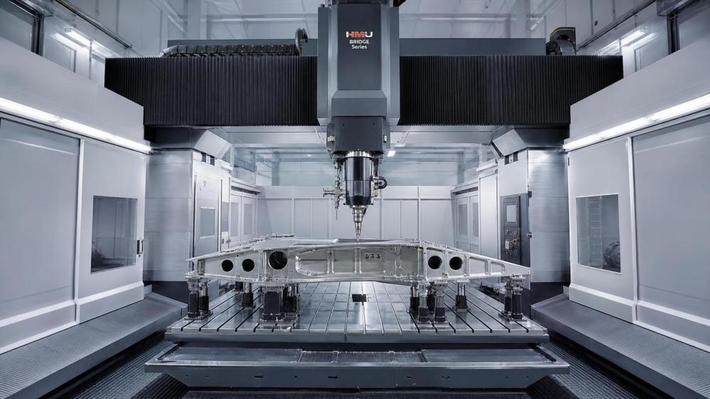
A bridge-type configuration is often selected when the workpiece is too large, too heavy, or too complex for a conventional trunnion-style 5-axis machine. The bridge spans the work zone while the table, saddle, spindle head, or a combination of these elements provides linear and rotary motion. This architecture can offer strong access to large prismatic parts and can support substantial fixture loads without forcing the component into an awkward vertical setup.
That does not mean every bridge machine is automatically rigid. The structural behavior depends on where the moving mass sits, how far the ram extends, the guideway arrangement, the bridge cross-section, drive layout, and the relationship between the spindle nose and the part. Two machines with similar X, Y, and Z travels may behave very differently during heavy roughing or five-axis contouring.
For large parts, machine travel should include usable clearance, not merely nominal movement. Leave room for fixture plates, tombstones, locating hardware, probe access, tool length, chip evacuation, and safe loading. A workpiece that technically fits but leaves no clearance for tooling or inspection is not a practical fit.
Start With the Part, Not the Machine Specification Sheet
Before comparing suppliers, create a short representative-part package. It should include a current drawing, material, blank condition, finished weight, maximum envelope, annual volume, critical tolerances, expected cutting time, and a note identifying the features that currently require multiple setups or manual intervention.
This package exposes issues that broad machine specifications tend to hide. A forged steel component may need high torque and stable low-speed cutting. An aluminum aerospace structure may demand rapid axis motion, high dynamic accuracy, and reliable chip removal from deep pockets. A cast pump or valve body may require access to compound-angle bores while managing interrupted cuts and abrasive scale. The same bridge-type machine is rarely ideal for all three cases.
Pay particular attention to the starting condition of the workpiece. Large castings and forgings may arrive with variable stock allowance, residual stress, hard spots, or datum surfaces that are not dependable. If the process relies on one light finishing pass after aggressive roughing, the machine must recover position and maintain thermal behavior well enough to protect the finished geometry. That requirement has more value than a headline rapid-traverse number.
Rigidity Is About the Complete Cutting Loop
Machine rigidity is often discussed as if it were a single property. In practice, it is the combined stiffness of the spindle, ram, bridge, guideways, rotary axes, table, fixture, workpiece, toolholder, and cutting tool. The weakest element governs the result.
Long-reach tools make this especially important. A machine may perform well on a shallow face-milling demonstration, then chatter when using an extended end mill to finish a deep cavity wall. Ask to see a cut that resembles the difficult portion of your process: similar material, tool projection, radial engagement, axial depth, and workholding condition. A generic test piece does not answer that question.
Ram extension deserves close scrutiny. A long quill or ram is useful for reaching deep features, but it changes the structural loop. Determine whether the required machining positions force the machine near its maximum extension, and ask the builder how spindle performance, axis acceleration, and geometric accuracy are verified in that condition.
Fixture design belongs in this discussion early. Large parts can distort when clamped too aggressively, particularly thin-wall weldments, aluminum structures, and heat-treated components. A rigid machine cannot compensate for an unstable or over-constrained fixture. The preferred setup is often one that locates consistently, supports cutting loads close to the operation, and allows the part to relax without creating a false datum condition.
Do Not Treat Accuracy and Repeatability as the Same Claim
Positioning accuracy, repeatability, volumetric accuracy, and finished-part capability are related but not interchangeable. A machine can repeatedly return to an imperfect position. It can also show acceptable axis results while producing geometric error once rotary motion, thermal growth, and a real fixture are involved.
For tight-tolerance work, ask how the supplier measures and compensates geometric error across the usable volume. Laser calibration, ball-bar testing, rotary-axis checks, and volumetric compensation can all be relevant, but the useful question is not simply whether a test was performed. Ask when it was performed, what conditions applied, what acceptance limits were used, and how results are documented after installation.
Rotary-axis behavior needs equal attention. Five-axis machining depends on correct center-of-rotation data, backlash control, clamping stability, and smooth interpolation between linear and rotary axes. On large parts, even a small angular deviation can produce a meaningful positional error at the cutting point. Review the intended orientation range rather than assuming that a published A/C or B/C axis configuration will provide easy access everywhere.
A good acceptance trial includes more than a dimensional report from one finished component. It should demonstrate a defined machining sequence, controlled warm-up conditions, representative tool lengths, probing, and inspection of the features that matter. If the process requires reorientation and finish machining on several faces, those transitions should be part of the test.
Thermal Stability Often Decides the Long Shift
Many selection decisions are made around a short demonstration cut. Production behavior over several hours is more revealing. Spindle heat, coolant temperature, hydraulic systems, motors, ambient changes, and repeated axis movement can shift machine geometry. On a large work envelope, small changes at the machine structure can appear as measurable error at the part.
Look for a clear thermal-management approach: spindle cooling where appropriate, controlled coolant practices, temperature sensing, compensation methods, and a defined warm-up routine. The exact design differs by builder, so it is better to ask how thermal performance is validated than to seek a specific feature list.
Thermal compensation is useful, but it should not be treated as permission to ignore process control. A stable installation environment, sensible machining sequence, consistent coolant conditions, and in-process measurement normally matter just as much. A finishing operation run immediately after heavy roughing may need a dwell, a probe update, or a different sequence to protect the result.
Spindle Selection Should Follow Material and Tooling Strategy
High spindle speed is attractive, especially for aluminum and smaller finishing tools. Yet large tight-tolerance parts frequently need torque, stable power delivery, and a spindle interface capable of carrying heavy tools with low runout. Steel forgings, ductile iron castings, and nickel-based alloys impose a different load profile from thin-wall aluminum machining.
Evaluate spindle torque and power curves at the speeds where your tools will actually run. Also confirm the spindle taper or interface, toolholder availability, pull-stud standard, permissible tool mass, tool length, and balancing requirements. A spindle selection that is excellent for fast finishing may not be suitable for large-diameter roughing tools or extended boring bars.
Tool center point control, look-ahead capability, smoothing functions, and postprocessor quality matter during simultaneous five-axis machining. Poorly tuned motion can leave witness marks, create inconsistent feed at changing tool orientations, or extend cycle time. Ask whether the supplier can support postprocessor validation using your CAM system and a representative part path. The machine, control, CAM output, cutting tool, and fixture must work as one process.
Workpiece Access and Chip Control Are Easy to Underestimate
Bridge-type layouts can provide excellent access, but access must be checked with the actual part and fixture model. A rotary table may improve five-side machining while reducing clearance for loading. A fixed table may support larger workpieces but can require more complex fixturing or additional setups. Some parts are best served by a machine that supports a rotary axis only when needed, rather than making every operation depend on it.
Consider how the component will enter and leave the machine. Crane clearance, door opening, loading height, fixture change time, pallet arrangements, and safe access for operators all affect real throughput. A very large machine can create an expensive handling problem if the facility lacks appropriate lifting capability or if the fixture must be assembled inside the enclosure.
Chip evacuation also affects accuracy. Aluminum chips can pack in deep pockets; cast iron dust requires containment and disciplined maintenance; long steel chips can interfere with fixtures and probing. Check conveyor layout, coolant filtration, washdown coverage, enclosure sealing, and access for cleaning. A machine that cannot stay clean during long cycles will eventually lose reliability.
Build Inspection Into the Selection Decision
Large parts are expensive to remove from the machine, transport to a coordinate measuring machine, discover as nonconforming, and then re-fixture for correction. Probing does not replace final inspection, but it can reduce risk by confirming datum position, detecting stock variation, updating work offsets, checking critical intermediate features, and validating the part before unclamping.
Probe accessibility should be reviewed using the same digital setup model used for cutting. A probe that cannot reach a bore, a sealing face, or a critical datum under the actual fixture is of limited value. Also check whether the control can manage the probing cycles, compensation logic, reporting needs, and operator workflow without relying on manual calculations.
For very demanding geometry, establish a clear division between in-machine verification and external metrology. In-machine probing is strongest when it supports process decisions. Final acceptance may still require a controlled inspection plan, traceable instruments, and a method for correlating machine-side measurements with external results.
A More Useful Comparison Method
Instead of ranking machines by travel, spindle speed, and purchase price, score each candidate against the operations that create the most quality risk. A simple weighted review can make the discussion more disciplined:
- Ability to machine the full part and fixture envelope with practical clearance.
- Structural behavior during the heaviest and longest-reach cutting operations.
- Thermal control over the expected cycle length.
- Rotary-axis range, clamping, accuracy, and access to critical faces.
- Spindle torque, speed range, tooling interface, and runout suitability.
- Probe integration, external inspection compatibility, and reporting needs.
- Control, CAM postprocessor support, automation readiness, and service response.
- Foundation, power, coolant, lifting, and maintenance requirements at the installation site.
Use a common representative part for every supplier discussion. This prevents a familiar problem: each builder demonstrates the type of work that makes its own machine look strongest, while the difficult operations in your process remain untested.
Resources such as Global Industrial Machining & Piping Equipment Network (IMPE) can help organize comparison points around machining capability, tolerance control, material behavior, inspection, and supplier documentation. The useful outcome is not a longer list of features; it is a clearer link between the component drawing, the proposed process, and the evidence supporting it.
When a Bridge-Type Machine Is Not the Best Answer
A bridge-type configuration is not automatically the right purchase simply because the part is large. If most work is rotational, a mill-turn or large turning center may reduce handling and provide better process control. If the part is mostly planar and requires limited angular features, a three-axis or four-axis machine with well-designed fixtures may be more economical and easier to qualify.
Likewise, a five-axis machine may be underused when volumes are low, geometry is simple, and the existing process already holds tolerance with predictable setups. The value of five-axis machining comes from reducing re-fixturing, improving feature relationships, reaching difficult surfaces, and shortening process flow. If those benefits do not address a real production constraint, the added complexity may not pay back.
Final Decision: Buy Evidence, Not Potential
The strongest selection decision is based on demonstrated process capability: a representative cut, realistic fixturing, the intended tooling strategy, documented accuracy checks, and an inspection plan that reflects the drawing. Ask what happens after installation as well. Calibration support, application engineering, spare parts, control training, and service access can determine whether a capable machine remains capable over time.
When evaluating bridge type 5 axis machining centers, prioritize the machine that can repeatedly produce your hardest critical features under production conditions. That approach is less glamorous than comparing catalog numbers, but it is the one most likely to protect tolerance, delivery performance, and the cost of every part that follows.
Related News
- How to Assess a Rigid Coupling Supplier for Bore Accuracy and Traceable QualityOct 08, 2026Tribology & Kinematics Expert
- Titanium Alloys Compared: Balancing Strength, Corrosion Resistance, and MachinabilityOct 08, 2026CNC Kinematics Architect
- Where Ductile Iron Dismantling Joints Reduce Alignment Risk in Water PipelinesOct 08, 2026Pipeline Metallurgy Scientist
- Selecting a Precision Bearing Sleeve: Fits, Runout, and Material ChoicesOct 08, 2026Tribology & Kinematics Expert
- Face Milling Cutters: How Insert Geometry Affects Finish on Steel and AluminumOct 08, 2026CNC Kinematics Architect
- Single-Acting Cylinders for Clamping: Stroke, Force, and Return Spring ConsiderationsOct 07, 2026Fluid Power Control Strategist