
Selecting Machine Vises That Maintain Clamping Accuracy in 5-Axis Machining
Selecting Machine Vises That Maintain Clamping Accuracy in 5-Axis Machining
In 5-axis machining, a vise is not simply a workholding accessory. It becomes part of the accuracy system formed by the machine structure, rotary axes, spindle, cutting tool, program, and inspection process. A part can be located correctly at setup and still drift out of tolerance when the machine changes tool orientation, applies side loads from a long-reach cutter, or repeatedly indexes through complex positions. That is why selecting Machine Vises requires more than comparing jaw width, opening range, or advertised clamping force.
For project leaders responsible for delivery, capacity, and quality risk, the practical question is whether a vise will hold a workpiece consistently throughout the real machining cycle. The answer depends on repeatability, jaw geometry, body stiffness, workpiece support, accessibility, mounting interface, chip management, and the discipline of the setup method. A poor choice can create defects that look like programming, tool-life, or machine-calibration problems. In reality, the source may be a part that moved slightly, lifted under clamping, or distorted after release.
Why 5-Axis Workholding Changes the Selection Criteria
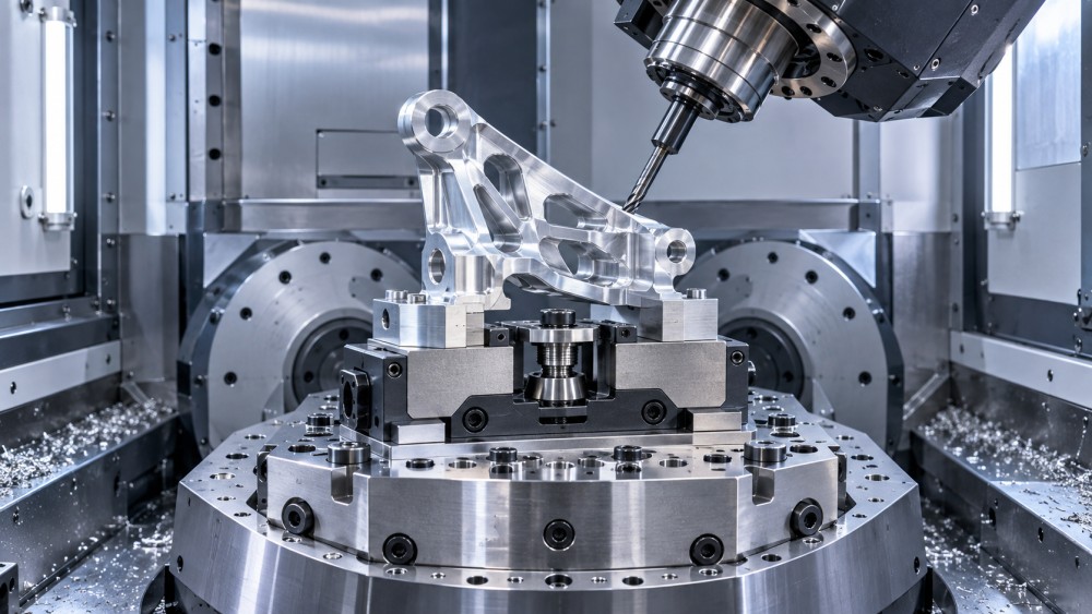
A conventional three-axis milling operation can often tolerate a vise arrangement that blocks several sides of a part. In 5-axis machining, the goal is usually different: machine as many features as possible in one setup while allowing the spindle to approach from multiple angles. The vise must therefore expose the part while resisting forces that do not act in a single predictable direction.
This changes the balance between holding force and access. A large conventional vise may provide a familiar, rigid platform, but its high jaws and broad body can restrict tool paths, increase the likelihood of holder interference, and force additional setups. A low-profile 5-axis vise can improve access to five faces, yet it may be unsuitable if the workpiece has thin walls, an unstable clamping surface, or heavy roughing loads. The best option is not automatically the smallest vise or the one with the highest rated force. It is the arrangement that gives enough restraint without hiding critical surfaces or deforming the blank.
The consequences are especially visible on aerospace brackets, valve bodies, robotic joints, mold inserts, forged structural parts, and complex hydraulic components. These parts often combine deep pockets, angled holes, thin sections, and datum features that must remain related after several rotary-axis movements. For such work, a vise selection decision should begin with the part drawing and machining sequence, not with the catalog page.
Start with the Workpiece, Not the Vise
Before comparing suppliers or models, define the surfaces that can safely carry clamping load. This is more involved than identifying the largest flat area. The usable gripping zone must have sufficient thickness, material integrity, and dimensional allowance. Castings may include draft, local skin variations, or interrupted surfaces. Forgings can have scale or uneven stock. Saw-cut bar stock may not provide a reliable datum until it has been faced. When the initial gripping surface is uncertain, a dedicated soft-jaw operation or sacrificial clamping tab may be the more controlled choice.
Material behavior matters as much as shape. Aluminum, thin stainless steel, and softer nonferrous materials can mark or distort under concentrated jaw pressure. Hardened steels may resist indentation but transmit cutting vibration differently. Ductile iron and cast components need careful support because their external geometry may not be ideal for direct gripping. A project team should ask whether dimensional stability is required while clamped, after unclamping, or after a later heat-treatment or finishing step. Those are not the same requirement.
The machining route also determines the loading condition. Light finishing of a compact billet is a very different application from high-material-removal roughing with an extended cutter. Axial force, radial force, interrupted cuts, tool entry direction, and rotary-axis acceleration can all affect how a workpiece behaves. If roughing and finishing are done in the same setup, the workholding decision must satisfy the roughing operation first while still preserving access for finishing.
The Clamping Characteristics That Actually Affect Accuracy
Clamping force is important, but it is not a complete indicator of security. The useful question is how that force is transferred into the part. A vise with a pull-down mechanism can help seat the workpiece against the locating surface as the movable jaw closes. Without controlled downward action, the part may climb or tilt slightly, particularly when there is burr, chip contamination, or an uneven contact face. The resulting error can be small enough to escape visual detection and large enough to affect critical feature relationships.
Jaw design deserves close attention. Serrated jaws provide strong grip on rough stock but can damage finished surfaces and concentrate stress. Smooth jaws protect surfaces but may not be appropriate for aggressive cutting unless sufficient contact area and support are available. Step jaws, machinable soft jaws, dovetail jaws, and custom contour jaws each solve different problems. For high-value parts, the cost of machining dedicated jaws may be lower than the cost of repeated adjustments, scrap investigation, or an extra setup.
Repeatability is another area where teams should look beyond broad marketing claims. It includes the consistency of the fixed jaw reference, the condition of the screw or wedge mechanism, jaw seating, base location, and the operator’s ability to reproduce the same setup. A vise may be mechanically well made yet perform inconsistently if its locating surfaces are difficult to clean, if jaws are swapped without verification, or if clamping torque is applied by feel alone. For repeat work, define the clamping method in the setup documentation: jaw type, gripping depth, workpiece stop, torque practice, and required verification points.
Stiffness includes the whole mounting chain
A rigid vise mounted poorly is not a rigid system. Review the connection from machine table or pallet to baseplate, from baseplate to vise, and from vise to workpiece. On trunnion-style machines, the available envelope changes continuously as the rotary axes move. A tall vise can move the workpiece farther from the rotary center, reducing usable travel and increasing the effect of any small compliance in the stack. It can also create collision risks that are not obvious in a static setup view.
Zero-point or quick-change pallet systems can reduce setup time and improve repeat placement, but they do not eliminate the need to assess rigidity. The team should confirm interface compatibility, locating pattern, allowable load, pull-down behavior, and access for tightening or cleaning. Where multiple identical vises are used on a tombstone, pallet, or fixture plate, their actual installed height and reference positions should be checked as an assembly. Nominal dimensions alone do not guarantee interchangeable production results.
Low Profile Does Not Mean Low Risk
Low-profile Machine Vises are popular in 5-axis cells because they provide side access and make simultaneous machining more feasible. Their value is real, but reduced jaw height also reduces the margin for error. A shallow grip can be entirely suitable for a stable billet with a well-planned toolpath; it can be risky for a tall, narrow, irregular, or thin-walled component. The part may rotate under lateral force, flex around the gripping area, or become vulnerable to accidental tool contact.
Consider the center of gravity and the moment created by cutting forces. A workpiece that projects far above the jaws behaves like a lever. Increasing clamping force may not solve that problem; it can simply deform the local grip zone while leaving the part insufficiently supported. In these cases, a support point, fixture rail, secondary locating feature, or purpose-built fixture may be more appropriate than pushing a standard vise beyond its comfortable application range.
Accessibility must also be evaluated with the actual tool assembly, not only the cutter. The spindle nose, holder, extension, coolant delivery, probe, and tool-change envelope all need clearance. CAM simulation is valuable, but it should reflect the real vise, jaws, bolts, stops, and baseplate. Simplified fixture models can leave out precisely the details that cause collisions on a five-axis machine.
A Practical Evaluation Matrix for Project Decisions
When several vises appear technically acceptable, a short evaluation matrix can prevent the decision from becoming a price comparison. The criteria below are useful because they connect workholding features to operational consequences.
Do Not Separate Vise Choice from Inspection Strategy
The most reliable way to validate a workholding choice is to inspect the conditions it is intended to control. This may include checking the seating face before machining, probing the workpiece after clamping, measuring critical relationships while still fixtured where feasible, and comparing results after release. If a thin component changes shape after unclamping, the issue is not necessarily machining error. It may be residual stress, inadequate support, excessive clamping load, or a combination of all three.
For repeat programs, use first-article findings to refine the vise setup rather than treating workholding as fixed. Changes might include a wider contact jaw, a different gripping location, a machined support feature, revised roughing order, or a reduced force setting supported by better geometry. This is particularly relevant for castings and forgings, where incoming stock variation can be greater than in billet machining. Material certificates and inspection records are useful, but they do not replace confirmation that each workpiece seats predictably in the chosen fixture.
Common Decisions That Create Avoidable Problems
One common mistake is selecting a vise solely around maximum opening capacity. A wide opening may be necessary, but it does not confirm that the moving jaw remains suitable for the intended load, or that the part has adequate support at that span. Another is assuming that a higher clamping-force figure automatically means better control. On delicate workpieces, excessive force can introduce the very dimensional change the process is meant to avoid.
Teams also underestimate contamination. Chips beneath a part, burrs on a jaw, coolant residue on locating surfaces, and damaged jaw serrations can all affect seating. In a 5-axis environment, the fixture may rotate into positions where chips accumulate differently from a conventional horizontal setup. Cleaning access and drainage are therefore design issues, not housekeeping details.
Finally, avoid buying a vise family without confirming its ecosystem. The availability of compatible jaws, locating stops, risers, baseplates, replacement components, and documented mounting information affects whether the system can be standardized across machines. For project schedules, standardization can be more valuable than a marginal feature advantage on one isolated setup.
Make the Decision at the Process Level
A sound vise decision connects the drawing, blank condition, machining sequence, machine kinematics, and inspection plan. It should state what surfaces are gripped, why they can tolerate the load, how the part is located, what tool access is retained, and how repeatability will be verified. If these questions cannot be answered clearly, the workholding concept is not ready for production regardless of how capable the machining center may be.
Global Industrial Machining & Piping Equipment Network (IMPE) approaches these decisions as part of a wider industrial capability review. In precision machining, equipment selection, material behavior, fixture design, tolerance control, and inspection all influence the same final result. Before committing to a vise configuration, project teams should review the actual part model, machining loads, fixture interface, available metrology, expected production volume, and requirements for traceable process documentation. That review usually reveals whether a standard low-profile vise is sufficient or whether the application calls for engineered jaws, added support, or a dedicated fixture.
Related News
- How to Assess a Rigid Coupling Supplier for Bore Accuracy and Traceable QualityOct 08, 2026Tribology & Kinematics Expert
- Titanium Alloys Compared: Balancing Strength, Corrosion Resistance, and MachinabilityOct 08, 2026CNC Kinematics Architect
- Where Ductile Iron Dismantling Joints Reduce Alignment Risk in Water PipelinesOct 08, 2026Pipeline Metallurgy Scientist
- Selecting a Precision Bearing Sleeve: Fits, Runout, and Material ChoicesOct 08, 2026Tribology & Kinematics Expert
- Face Milling Cutters: How Insert Geometry Affects Finish on Steel and AluminumOct 08, 2026CNC Kinematics Architect
- Single-Acting Cylinders for Clamping: Stroke, Force, and Return Spring ConsiderationsOct 07, 2026Fluid Power Control Strategist