
CNC Spindles: Matching Speed, Torque, and Duty Cycle to Machining Workloads
Selecting CNC spindles is a project-critical decision that directly affects machining capacity, part quality, cycle time, and operating cost. For engineering leaders managing demanding production programs, the right balance of speed, torque, and duty cycle must match material type, cutting strategy, tooling, and expected workload.
The most important decision is rarely choosing the spindle with the highest published RPM or peak power. It is choosing a spindle whose usable torque, thermal behavior, and continuous operating capability fit the production work it must perform.
A mismatch can create recurring bottlenecks: poor metal removal rates, chatter, tool breakage, inconsistent finishes, overload alarms, unplanned maintenance, and missed delivery commitments. These issues become expensive when they appear across multiple machines or long-running programs.
For project managers, spindle selection should therefore be treated as a workload-matching exercise. Review the actual parts, materials, cutters, cycle-time targets, shifts, and future product mix before approving equipment specifications.
Start With the Machining Workload, Not the Spindle Catalog
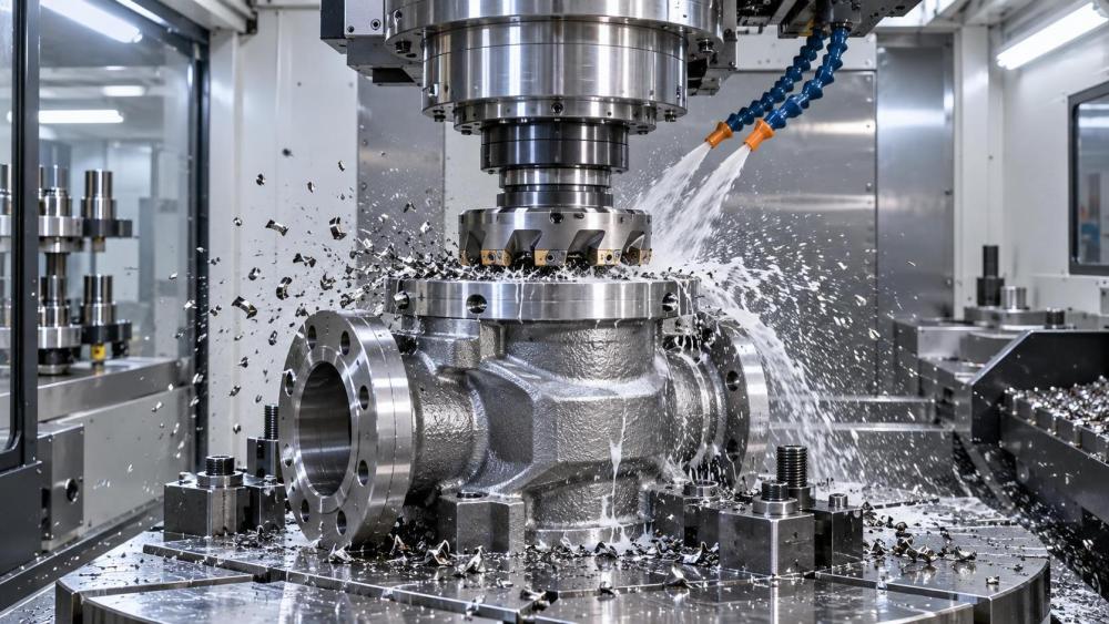
Before comparing CNC spindles, define what the machine must produce. A spindle suitable for aluminum aerospace components may be a poor fit for steel valve bodies, forged shafts, or large ductile iron castings.
Collect representative part data rather than relying on a single best-case component. Include material grades, stock condition, maximum tool diameters, hole sizes, cutting depths, finishing requirements, annual volume, and expected batch patterns.
Material behavior drives much of the spindle requirement. Aluminum generally benefits from high rotational speed and rapid feed capability, while alloy steel, stainless steel, titanium, and hardened materials need sustained torque and rigid cutting conditions.
Cast iron creates a different operating profile. It may not demand extreme spindle speed, but abrasive dust, interrupted cutting, heavy milling loads, and long machining cycles require robust bearings, sealing, cooling, and contamination control.
Also distinguish roughing from finishing. Roughing determines the required torque and power reserve, while finishing often determines speed range, runout, vibration behavior, thermal stability, and the ability to maintain surface quality repeatedly.
A project team should identify the process that imposes the greatest demand, not simply the process with the largest annual quantity. One difficult deep-pocket operation can determine whether a selected spindle becomes a production constraint.
Future workload matters as much as today’s drawings. If a machining cell is expected to absorb larger forgings, higher-strength materials, or more five-axis work, selecting only for current conditions can shorten the equipment’s useful life.
Understand the Difference Between Speed, Torque, and Power
Speed, torque, and power are related, but they answer different questions. Speed determines how fast the cutter rotates. Torque reflects turning force. Power describes the rate at which the spindle can perform cutting work.
High RPM is valuable when using small-diameter tools, especially in aluminum, composites, light alloys, mold finishing, and small-feature machining. However, speed alone does not guarantee productive cutting at larger diameters.
Torque becomes critical when cutting forces rise. Large face mills, indexable end mills, twist drills, boring tools, and aggressive roughing operations need enough torque to maintain programmed feed without stalling or excessive load.
The governing relationship is simple: as spindle speed rises, available torque often declines unless power increases proportionally. Published peak torque values can therefore be misleading if they occur only at low speed.
Project managers should request a spindle torque-power curve, not merely a headline RPM and motor power rating. The curve shows usable performance across the operating range where real tools will run.
For example, a spindle rated at 18,000 RPM may appear versatile. Yet if its torque falls sharply around the common operating range for larger steel cutters, it may force reduced depth of cut or slower feed rates.
Conversely, a lower-speed spindle with a broad constant-power range may remove substantially more material from steel or cast iron. The correct choice depends on cutting conditions, not on which specification appears more advanced.
Consider the largest cutter and most demanding roughing operation carefully. These are often the clearest indicators of required low- and mid-range torque, particularly on heavy industrial components.
Choose the Right Speed Range for Tool Diameter and Material
Spindle speed should be calculated from cutting speed and tool diameter, then checked against the machine’s intended feed rate. This avoids selecting a spindle based on generic assumptions about high-speed machining.
Small carbide tools can require high RPM to reach effective surface speed. In contrast, a large face mill may operate efficiently at much lower speed while demanding significantly greater torque and stable power delivery.
For aluminum parts, high-speed CNC spindles can reduce cycle time when machine dynamics, toolholders, coolant delivery, and CAM strategies also support high feed rates. The spindle must not be assessed in isolation.
For stainless steel and nickel alloys, increasing RPM beyond the recommended cutting zone can raise heat, accelerate tool wear, and create work hardening. Stable torque and controlled coolant application are usually more valuable.
Titanium machining requires particular caution. It produces high cutting forces and retains heat near the cutting edge. A spindle must support the intended speed range while maintaining rigidity and avoiding damaging thermal loads.
Hardened steel finishing may need relatively high speed with small tools, but the required torque can remain modest. This is why mixed production environments frequently need balanced spindle specifications rather than one extreme performance characteristic.
Do not confuse maximum speed with recommended operating speed. Running continuously close to maximum RPM can increase bearing stress, heat generation, noise, and maintenance exposure, especially under unbalanced tooling conditions.
Evaluate Torque Where Your Process Actually Cuts
The most practical spindle question is not “What is the maximum torque?” It is “How much torque remains available at the RPM required by our highest-load cutting operations?”
Ask process engineers to list the spindle speeds used by roughing tools, large drills, thread mills, boring heads, and heavy finishing cutters. Match these speeds against the supplier’s certified torque curve.
Torque reserve is important because real production is not perfectly uniform. Material hardness can vary, cast surfaces can be interrupted, fixtures may lose stiffness, and tool wear gradually increases spindle load.
A spindle operating close to its torque limit may still complete a test cut. In regular production, however, it leaves little margin for variation and makes cycle times, finishes, and tool life less predictable.
This reserve is particularly important for machined castings and forgings. Their skin condition, inclusions, residual stresses, and local hardness can create load changes that are not obvious in a nominal process plan.
For heavy milling, assess torque together with spindle taper, toolholder interface, machine structure, axis thrust, and fixture rigidity. A high-torque spindle cannot compensate for a weak mechanical system around it.
For drilling and tapping, review low-speed torque and control behavior. Large-diameter holes, deep holes, and synchronized tapping can place different demands on the spindle than high-speed contour milling.
Document the expected spindle-load percentage for critical cuts. A reasonable operating margin improves process resilience and provides room for tool wear, material variability, and future productivity improvements.
Duty Cycle Determines Whether Performance Is Sustainable
Duty cycle is often overlooked during equipment procurement because catalogs emphasize peak power, maximum speed, and acceleration. Yet duty cycle determines whether those capabilities can be sustained through the planned production schedule.
A spindle may deliver impressive peak output for short bursts, then require reduced load or recovery time. This is acceptable for intermittent machining but unsuitable for continuous roughing or unattended multi-shift production.
Define the operating pattern in practical terms: cutting minutes per hour, high-load roughing duration, idle intervals, tool-change frequency, shift count, and whether the machine will run lights-out during nights or weekends.
Continuous-duty requirements are common in production of hydraulic manifolds, pump housings, gearbox components, valve bodies, and general industrial parts. These programs often involve repeated cycles with limited cooling opportunities.
Spindle cooling design must be reviewed as part of duty-cycle capability. Liquid cooling, chiller capacity, coolant temperature control, enclosure temperature, and ambient shop conditions all influence long-term thermal performance.
Thermal growth can affect dimensional accuracy even when a spindle does not trigger an alarm. This matters for close-tolerance bores, bearing seats, sealing surfaces, precision faces, and parts requiring reliable inspection results.
Ask suppliers whether stated power and torque are S1 continuous ratings, short-duration ratings, or peak values. Procurement documents should require clear definitions because marketing figures are not always directly comparable.
For critical projects, request evidence from comparable applications. Service history, thermal test data, duty-cycle documentation, and installed-base references provide stronger assurance than nominal catalog specifications alone.
Match Spindle Design to the Machine Architecture
CNC spindles operate within a complete machine system. Their performance is affected by machine mass, axis acceleration, guideway design, ballscrew or linear-drive capability, table load, fixture layout, and controller tuning.
A high-speed spindle in a heavy-duty machining center may be useful for certain finishing tasks, but it cannot automatically transform the machine into a productive high-speed machining platform for every part.
Likewise, a powerful spindle on a lightweight structure can create chatter when cutting forces rise. The result may be poor surface finish, reduced tool life, noise, and conservative cutting parameters that reduce expected output.
Tool interface selection is also important. BT, CAT, HSK, and Capto-style systems offer different benefits in rigidity, balance, automatic tool changing, high-speed suitability, and torque transmission.
For high-RPM work, balanced toolholders and accurate assembly procedures are essential. Imbalance increases vibration, bearing load, and finish variation, while also reducing confidence in running near the spindle’s upper speed range.
For high-torque machining, evaluate toolholder grip, pull-stud design, clamping force, and interface condition. Tool slip or poor seating can damage both tools and spindle components during demanding cuts.
Five-axis machines require additional attention because tool orientation changes cutting forces and reach conditions. A spindle chosen for vertical three-axis cutting may behave differently when machining deep features at compound angles.
Consider Bearings, Lubrication, and Contamination Risk
Spindle reliability depends heavily on bearing condition. Bearing preload, lubrication method, balance quality, temperature control, and shock exposure influence both machining accuracy and the total cost of ownership.
High-speed CNC spindles commonly use precision angular-contact bearings, while some heavy-duty applications may use different bearing arrangements to prioritize load capacity, stiffness, or low-speed torque behavior.
Contamination is a major risk in machining environments. Cast iron dust, abrasive particles, coolant mist, chips, and improperly maintained air systems can compromise seals, cooling pathways, tool clamping, and bearing life.
For cast iron, graphite-rich materials, and abrasive composites, assess enclosure management and air-purge provisions. A spindle that performs well in a clean demonstration may require enhanced protection in actual production.
Lubrication requirements should align with the maintenance capability of the plant. Oil-air systems, grease-packed bearings, and automated lubrication approaches have different service expectations, failure modes, and monitoring needs.
Include spindle maintenance in project planning from the beginning. Access for service, qualified technician availability, spare spindle lead times, chiller support, and alarm diagnostics can affect recovery after an unexpected failure.
A lower initial purchase price may be outweighed by high downtime exposure. For production-critical cells, evaluate repair turnaround, local service coverage, warranty conditions, and the option of holding a spare spindle.
Use a Practical Selection Matrix for Procurement Decisions
Project teams can improve decisions by scoring CNC spindles against documented production needs. This converts technical claims into a transparent comparison that engineering, operations, quality, and procurement can review together.
Include speed range, torque at required RPM, continuous power rating, duty-cycle definition, taper type, thermal management, runout, bearing design, tool-change system, maintenance requirements, and supplier support.
Weight criteria according to the project’s commercial reality. A prototype cell may prioritize flexibility and speed range, while a high-volume production line may prioritize uptime, thermal stability, process consistency, and service availability.
Cycle-time estimates should use realistic cutting parameters, including tool changes, probing, acceleration limits, and load restrictions. The fastest theoretical spindle is not always the lowest-cost production solution.
Quality risk should be assigned a measurable value. Consider the cost of scrap, rework, delayed inspection, missed shipment dates, customer penalties, and loss of confidence when dimensional variation becomes recurring.
Request cutting trials using representative materials and tools whenever possible. Trials should include the critical roughing operation, not only a light finishing demonstration designed to make the machine appear exceptionally fast.
During trials, record spindle load, temperature behavior, vibration, surface finish, tool wear, cycle time, and dimensional repeatability. This data creates a more defensible capital-equipment decision than sales specifications alone.
Balance Capital Cost Against Long-Term Production Value
Spindle selection should be evaluated over the expected life of the machine. The relevant comparison includes purchase price, throughput, energy use, tooling consumption, maintenance, repair risk, and the cost of lost production.
A more capable spindle can justify its cost when it shortens high-volume cycles, enables one-setup machining, reduces secondary operations, improves tool life, or supports new work without requiring another machine investment.
However, over-specification also has a cost. Paying for extreme speed or specialized features that the production mix will rarely use can reduce project returns and introduce unnecessary maintenance complexity.
The best investment is usually a spindle that covers current critical operations with practical reserve and supports foreseeable work. It should not depend on operating at its absolute performance limit every day.
For multi-site organizations, standardizing compatible spindle configurations can simplify tooling strategy, training, maintenance planning, spare-parts management, and process transfer between plants or approved machining suppliers.
Conclusion: Select CNC Spindles Around the Work That Creates Risk
Effective CNC spindle selection begins with the real workload: material, tool diameter, cutting strategy, expected throughput, and operating schedule. Maximum RPM and peak power are useful references, but they are not sufficient decision criteria.
Engineering leaders should verify torque at working speed, continuous-duty capability, thermal stability, machine-system compatibility, and maintainability. These factors determine whether a spindle can sustain required productivity beyond a demonstration cut.
When speed, torque, and duty cycle are matched to the machining workload, manufacturers gain more predictable cycle times, stronger quality control, longer tool life, reduced downtime, and better return on capital equipment investment.