
5-Axis Trunnion Tables: Improving Access and Rigidity for Complex Parts
Complex parts often fail to machine efficiently for a simple reason: the cutting tool cannot reach the required surface at a favorable angle without becoming too long. A long tool assembly increases leverage between the spindle and the cutting edge. That leverage magnifies deflection, encourages chatter, weakens surface finish, and makes dimensional control less predictable. A trunnion-style five-axis arrangement addresses this problem by bringing the workpiece into the tool rather than asking the tool to reach around the workpiece.
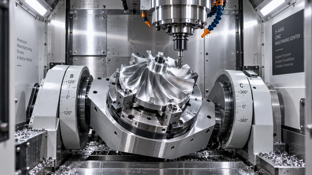
In a typical configuration, the table provides two rotary axes while the machine head supplies the linear axes. The part is mounted on a tilting cradle and rotary table, allowing several faces to be presented to a comparatively short, rigid tool. This layout is especially effective where cavities, compound angles, deep ribs, impeller-like forms, contoured mold surfaces, and intersecting bores must be machined in one coordinated setup.
Access Changes the Cutting Conditions
Tool access is often discussed as a geometric issue, but its main value is mechanical. When a workpiece is tilted toward the spindle, a short end mill may reach a wall or floor that otherwise requires an extended-reach holder. The increase in stiffness does not come from the rotary axes alone. It comes from reducing tool overhang, improving the tool's engagement position, and maintaining a more favorable force path through the holder, spindle, fixture, and table.
Consider a pocket with a tall surrounding wall. In a three-axis setup, the cutter may need enough stick-out to clear the wall while reaching the floor. Even when the programmed radial and axial engagement appear conservative, the long assembly can vibrate because the cutting force acts far from the holder support. With a trunnion table, the part can be indexed or simultaneously tilted so that the wall no longer blocks a shorter cutter. The same material removal task can then run with a more stable tool assembly, provided the new orientation does not create collisions or reduce fixture support.
Shorter tools also improve the reliability of probe and inspection relationships. A deep feature machined with an extended tool may show a different position at the bottom of the feature than at the entry due to bending under load. A touch probe can confirm geometry after cutting, but it cannot erase deflection that has already produced a tapered wall or an out-of-round bore. Better access reduces the source of that variation.
The Trunnion Is Part of the Structural Loop
A trunnion table should not be treated as a positioning accessory. During cutting, the structural loop includes the spindle, toolholder, cutting tool, workpiece, fixture, trunnion cradle, rotary bearings, machine table, and machine base. The least rigid connection governs the practical result. A compact part on a heavy fixture can still chatter if it is clamped high above the rotary centerline. Conversely, a well-supported casting may machine cleanly even under demanding cuts when the center of mass remains close to the trunnion pivot and the fixture transmits force directly into the table.
Rotary-axis size alone does not define rigidity. A large nominal table capacity says little about the stiffness of a particular setup. The relevant questions are where the part mass is located, how far the cutting zone sits from the tilt axis, whether the fixture introduces a cantilever, and whether the machining path reverses direction frequently. The table may hold the stated mass safely while still requiring reduced acceleration, lower feed demand, or a different orientation to control dynamic movement.
Tilting orientation also changes the direction of cutting force. Side milling a thin wall while the wall is poorly supported can push it away from the cutter regardless of table quality. Reorienting the part can place the force into a stronger section, direct it toward fixture support, or allow the use of a different cutter strategy. The objective is not simply to keep the tool perpendicular to a surface. It is to create a stable relationship among cutting force, stock condition, and clamping.
Rotary Centerline Distance Matters
The distance from the workpiece feature to the rotary centerline is a practical source of error and lost productivity. Features located far from the rotation center travel through a larger arc during indexing and simultaneous motion. This increases the consequences of rotary-axis positioning error, fixture variation, and model-to-part datum mismatch. It can also increase the required machine envelope and bring the workpiece closer to travel limits or enclosure boundaries.
Keeping the primary machining region near the center of rotation usually improves reach and reduces the tendency to create an unnecessarily tall setup. This does not require placing every feature exactly on the centerline. Large housings, forged shafts, and irregular castings often make that impossible. The useful discipline is to locate the most tolerance-sensitive surfaces and the highest-force cuts where the fixture and rotary system are most favorable, rather than centering an arbitrary exterior shape.
Indexing and Simultaneous Motion Solve Different Problems
Five-axis capability is sometimes assumed to mean that every feature should be cut with continuous rotary motion. That assumption can create avoidable complexity. Indexed machining rotates the part to a fixed angle, locks or clamps the rotary axes where the machine design permits, and then performs conventional linear-axis cutting. This approach is well suited to multiple prismatic faces, angled drill patterns, side ports, and features that benefit from a rigid stationary orientation.
Simultaneous machining is appropriate when the cutter must maintain changing contact with a contoured surface, avoid gouging around compound geometry, or control the tool axis through a continuous path. It is common in blisk-like shapes, sculptured molds, turbine components, and formed passages. The rotary axes then become active participants in feed motion, so axis smoothness, postprocessor quality, machine kinematics, and look-ahead settings have a direct effect on the finished surface.
The distinction matters because a simultaneous toolpath can look smooth in simulation while producing inconsistent marks on the machine. Small rotary reversals, insufficient smoothing, or unstable tool contact may leave witness patterns that resemble spindle vibration. Before changing feeds or replacing a tool, examine whether the marks align with changes in rotary direction or with rapid variation in tool-axis angle. That pattern points toward motion behavior rather than a purely cutting-related cause.
Fixture Design Determines Whether the Table Delivers Its Potential
A trunnion creates access only when the fixture does not block it. Fixtures designed for three-axis vertical machining frequently use broad base plates, tall locating blocks, and clamps placed around the upper perimeter. Transferring that design directly to a trunnion can eliminate the very angles the rotary axes are meant to provide. The fixture must expose the machining zones while preserving enough contact area to resist torque and cutting load.
Low-profile workholding is valuable, but low profile is not automatically rigid. A thin fixture plate with minimal clamping may give excellent tool clearance and poor support. The better arrangement establishes positive location with robust datum pads, controls side load through stops or shoulders rather than clamp friction alone, and uses clamps that remain secure through the full tilt range. The workpiece, fixture, and fasteners must be reviewed at the most demanding angles, not only at the loading position.
- A part that is stable at zero degrees may shift when tilted because gravity now acts across a different locating face or clamp direction.
- Hydraulic or pneumatic clamping requires hose routing that neither stretches nor pinches during rotation; external lines can also become collision hazards.
- Heavy castings need balance consideration. An off-center load can increase rotary drive demand and make rapid indexing less suitable, even when the fixture is structurally sound.
- Soft jaws or sacrificial supports should be placed where they resist cutting forces without trapping chips against finished surfaces.
Workholding verification should include the actual toolholders, not just the part and fixture models. A short cutter may be selected to gain stiffness, yet a large-diameter holder or pull-stud geometry can become the first collision point at high tilt angles. Collision checking must cover spindle housing clearance, tool-change position, rotary limits, clamp movement, probe approach paths, and the part's full swept volume.
Accuracy Is a Kinematic Chain, Not a Single Specification
Linear positioning accuracy and rotary positioning accuracy are often read as separate machine specifications. On a trunnion machine, their interaction matters more than either figure in isolation. A small angular error produces a larger linear displacement at a feature located farther from the rotation center. Tool center point control, rotary-axis calibration, work offset strategy, and the actual fixture location all influence the final feature position.
For close-tolerance multi-face work, establish datums that survive reorientation. A datum plane that is easy to probe at the loading angle may be inaccessible after tilt, while a side feature used as a secondary datum may carry casting variation or prior-operation error. Probing a stable locating feature before machining can identify gross setup variation, but probing strategy must match the tolerance scheme on the drawing. A probe cycle that only updates a work offset may be inadequate where the part is not seated consistently against its primary supports.
Thermal condition also affects repeatability. Rotary drives, bearings, and surrounding structures warm during prolonged motion and heavy cutting. Repeated finishing of a feature after a long roughing cycle can reveal a shift that is absent during a short prove-out part. When tolerance is narrow, separate roughing and finishing paths enough to stabilize the part and fixture, then use a consistent machine warm-up and verification routine. Recutting a surface after releasing a heavily loaded clamp can expose residual distortion in thin aluminum, stainless steel, or heat-treated components.
Surface Finish Symptoms Need Correct Diagnosis
Chatter marks, blend marks, scallops, and rotary transition lines are visually similar at first glance but do not have the same cause. Randomly spaced chatter commonly points to an unstable cutting system, excessive tool overhang, poor workpiece support, worn tooling, or an unsuitable engagement condition. Regular lines that occur at similar rotary angles may indicate axis interpolation behavior, insufficient path tolerance settings, or abrupt changes in tool-axis orientation.
A poor finish near the top of a tilted wall can result from changing effective cutter contact, not necessarily from reduced spindle rigidity. Ball-end finishing is particularly sensitive to contact location. Near the tool tip, cutting speed falls and rubbing becomes more likely. Tilting the part or tool axis slightly can move contact away from the center of the ball, but excessive tilt may create holder clearance issues or change the scallop pattern. The programmed tool orientation should therefore be reviewed alongside spindle speed, feed per tooth, step-over, and local surface curvature.
Programming Requires Machine-Specific Discipline
A trunnion machine has kinematic behavior that must match the control configuration and postprocessor. Rotary-axis directions, pivot locations, travel limits, preferred solution angles, and tool center point functions are not interchangeable between machines. A program that appears correct in generic CAM simulation can still rotate through an unexpected orientation if the machine definition or postprocessor transformation is wrong.
Reliable prove-out begins with the real work coordinate strategy and verified rotary home condition. Dry-running above the part is useful, but it should include the exact tool length offsets, fixture, clamps, and rotary range expected in production. During the first simultaneous moves, reduced feed and close observation of axis motion are appropriate because a kinematic error can move the part toward the tool or spindle housing rapidly.
Rotary-axis limits need attention before toolpaths are released. CAM software may solve a path by unwinding one axis, choosing an alternative tool orientation, or inserting a rotary reposition. Each behavior has consequences. An unwind may interrupt surface quality; an alternate orientation may reduce clearance; a reposition must occur safely away from the part. A short section of inaccessible geometry can be better handled as a separate indexed operation than forced into a continuous path that approaches a limit condition.
Maintaining Rotary Performance
Chip management is more important on a trunnion table than on a flat stationary setup because chips collect in changing pockets as the part rotates. Packed chips beneath a fixture or around a rotary sealing area can affect seating, contaminate locating faces, and increase wear. Coolant nozzles should reach the cutting zone through the expected tilt range, while air blast and washdown should clear areas where chips accumulate after indexing.
Periodic checks should focus on practical evidence: repeatability of a known probed feature after indexing, condition of fixture locating surfaces, unusual rotary noise, changes in backlash compensation behavior, and signs of coolant ingress or chip buildup. A gradual decline in multi-face positional agreement is not always a machine-axis problem. It can originate in a damaged fixture pad, trapped chip, loose clamp, changing material stock, or an offset entered against the wrong datum.
When the workpiece is oriented to shorten the tool, supported close to the rotary center, and held through a fixture that preserves access, a trunnion table turns five-axis motion into a stable machining condition rather than a purely geometric convenience.
Related News
- How to Assess a Rigid Coupling Supplier for Bore Accuracy and Traceable QualityOct 08, 2026Tribology & Kinematics Expert
- Titanium Alloys Compared: Balancing Strength, Corrosion Resistance, and MachinabilityOct 08, 2026CNC Kinematics Architect
- Where Ductile Iron Dismantling Joints Reduce Alignment Risk in Water PipelinesOct 08, 2026Pipeline Metallurgy Scientist
- Selecting a Precision Bearing Sleeve: Fits, Runout, and Material ChoicesOct 08, 2026Tribology & Kinematics Expert
- Face Milling Cutters: How Insert Geometry Affects Finish on Steel and AluminumOct 08, 2026CNC Kinematics Architect
- Single-Acting Cylinders for Clamping: Stroke, Force, and Return Spring ConsiderationsOct 07, 2026Fluid Power Control Strategist